Corsair 1000D Mod Focus: Making a Custom GPU SLI Terminal
September 12, 2018 | 13:00
Companies: #alphacool #amd #corsair #msi #nvidia #watercool
Connecting GPU blocks together in a custom loop has always been an interesting endeavour. "Back in the day" the options were very limited; thanks to most water blocks being not particularly modular you would either get creative with your regular fittings or if using multiples of the same block you could use fancy telescopic SLI fittings to join the ports. Out of this necessity were born some very interesting products and quite possibly the entire trend of hardline tubing (Bitspower's C47/48 push fittings were widely popular for this as it took off).
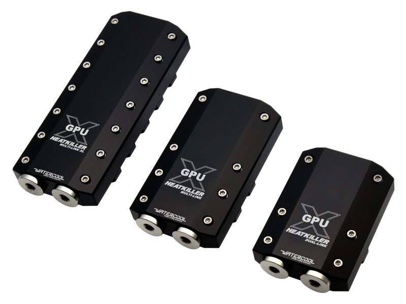
SLI/Crossfire terminals were one such innovation. Instead of using fittings to connect water blocks, you replace the ports with a single block of material that routes the fluid between them. This is all fairly standard fair now, with every manufacturer having their own variation and method of doing it, so it stands to reason that surely there's some modding potential here, right?
Why Custom?
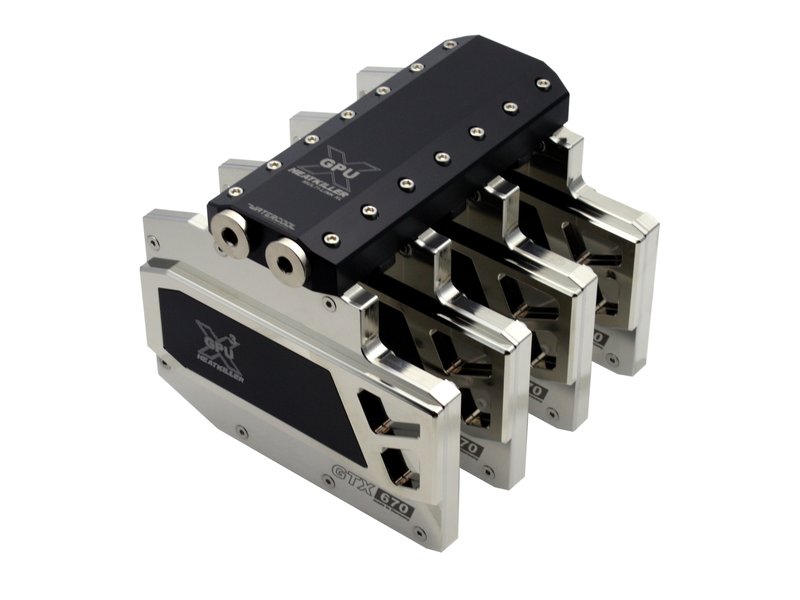
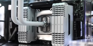
Our 1000D build has four GPUs included, of which three are in the front-facing Threadripper system, so they need connecting up. They're using gorgeous Watercooll Heatkiller blocks, but there's a minor snag: Watercool uses black acetal for its GPU water block terminals. This is fine normally, as acetal is strong, machines superbly, and is very chemically resistant, but it's very much opaque and given the placement would stand out against the abundant silver and clear acrylic in the build. The solution? Why not make a new terminal from scratch that's both clear and would allow for some alternative tube routing options?
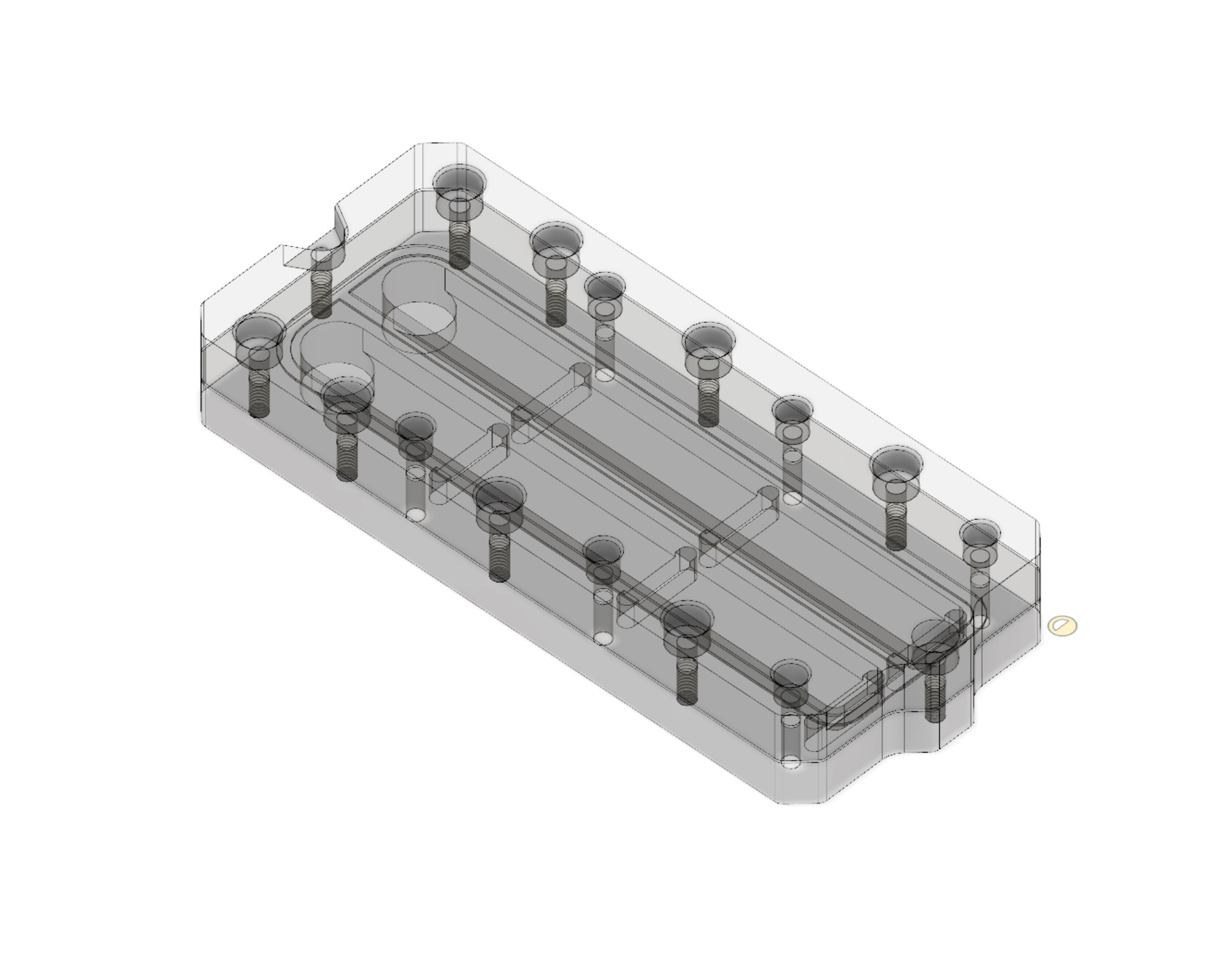
With a project like this, it's good to start by analysing how the stock system works. Watercool chose to keep its terminals very simple, with all the o-rings and screw threads present instead on the water blocks themselves. This is mighty convenient for producing custom variants, since there's less work to do and simply fewer variables that can go awry along the way. To ensure a tight seal against the blocks, all you need is a flat surface along with the correct mounting hole locations.
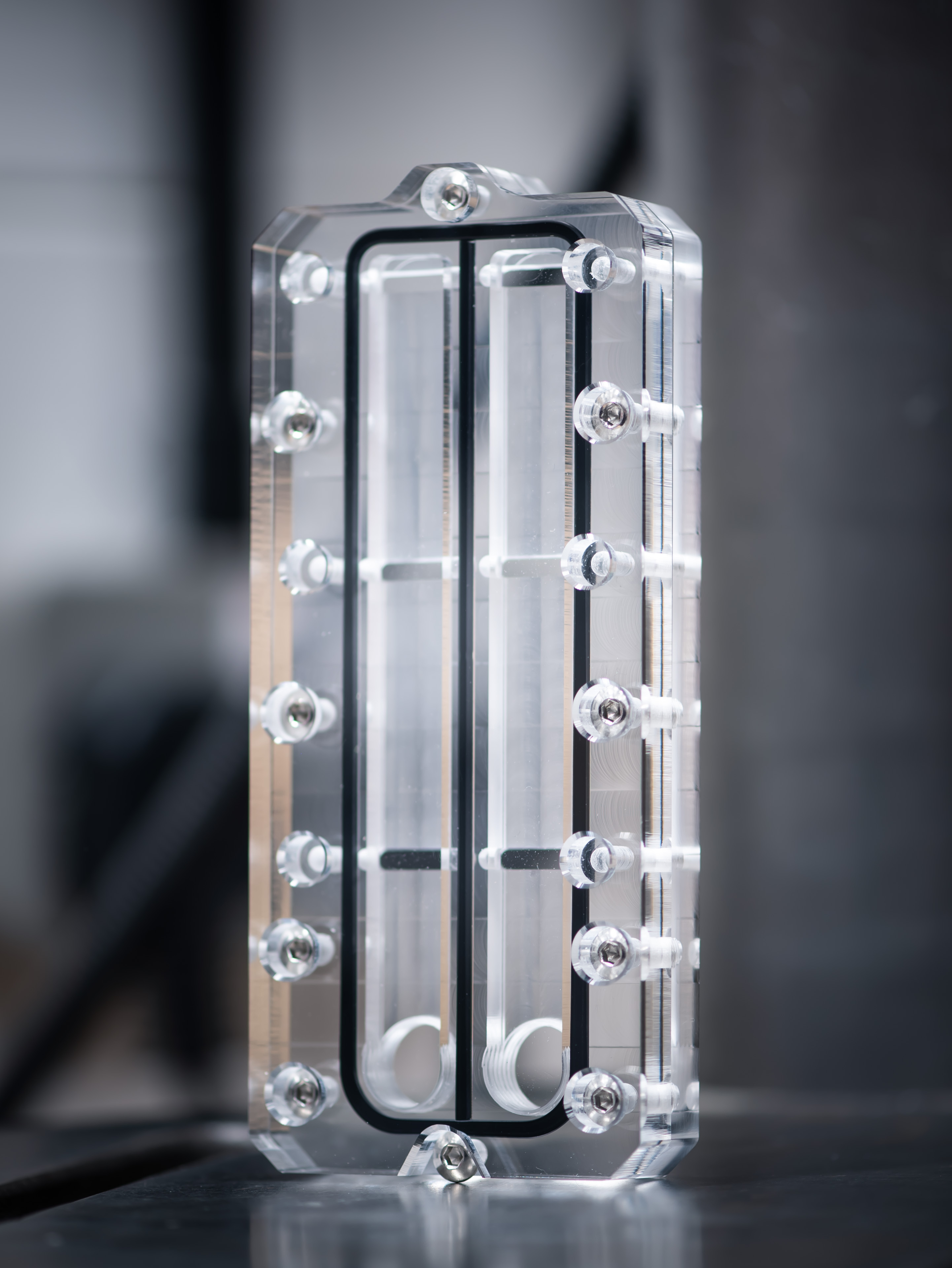
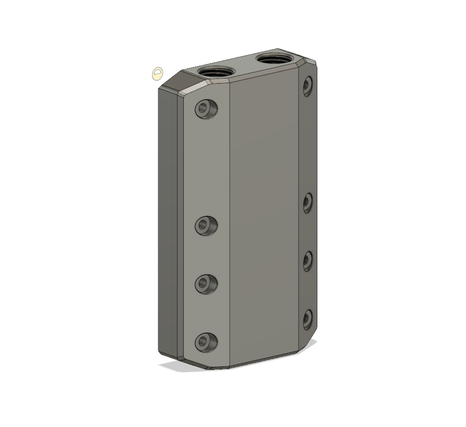
Since the terminal is a custom job, that also means we can make some changes to the design. I quite fancied having the in/out ports located on the rear of the bridge so as to give it a clean front, so I extended it down past the bottom-most card, leaving clearance for the fittings. As for making sure all the ports and mounting holes lined up correctly, that was a matter of careful measuring of the stock piece along with confirming any details with Watercool, who were happy to provide accurate values for things such as slot spacing. As for making sure the spacing between the GPUs themselves was kept accurate, I turned to the ATX specification (check out the article on making a custom motherboard tray for more info on this) and used the official spacing between PCIe slots.
Plan of Attack
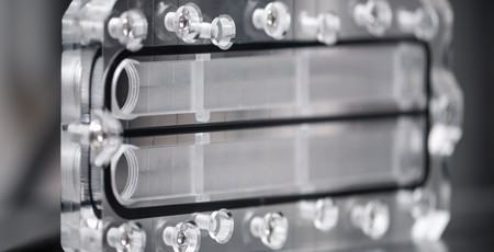
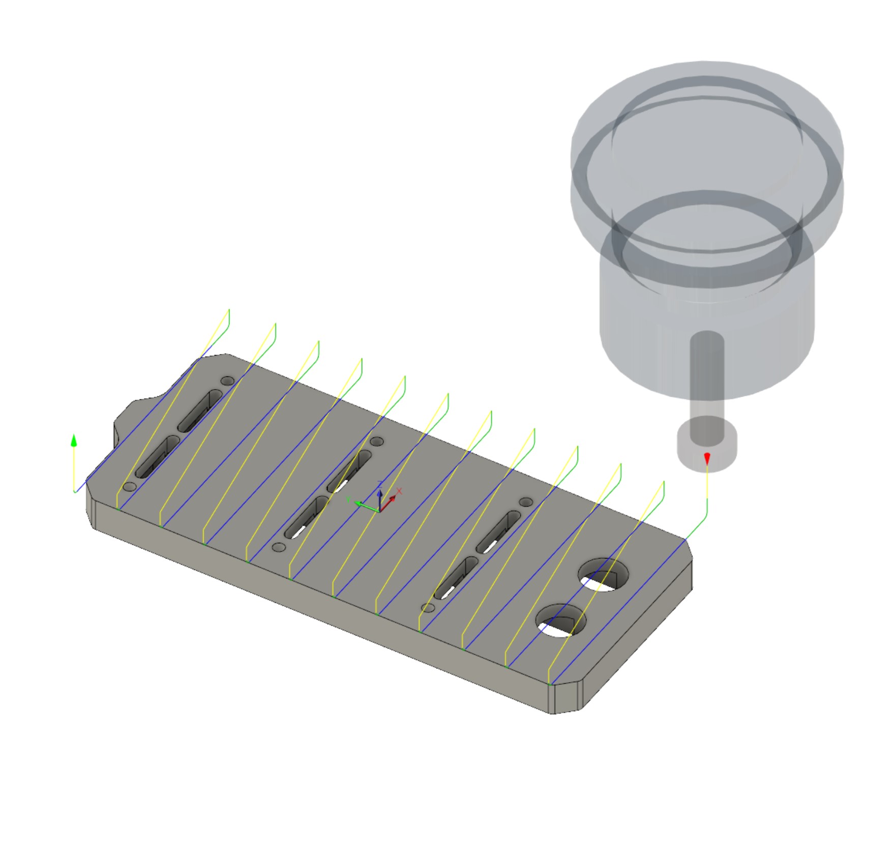
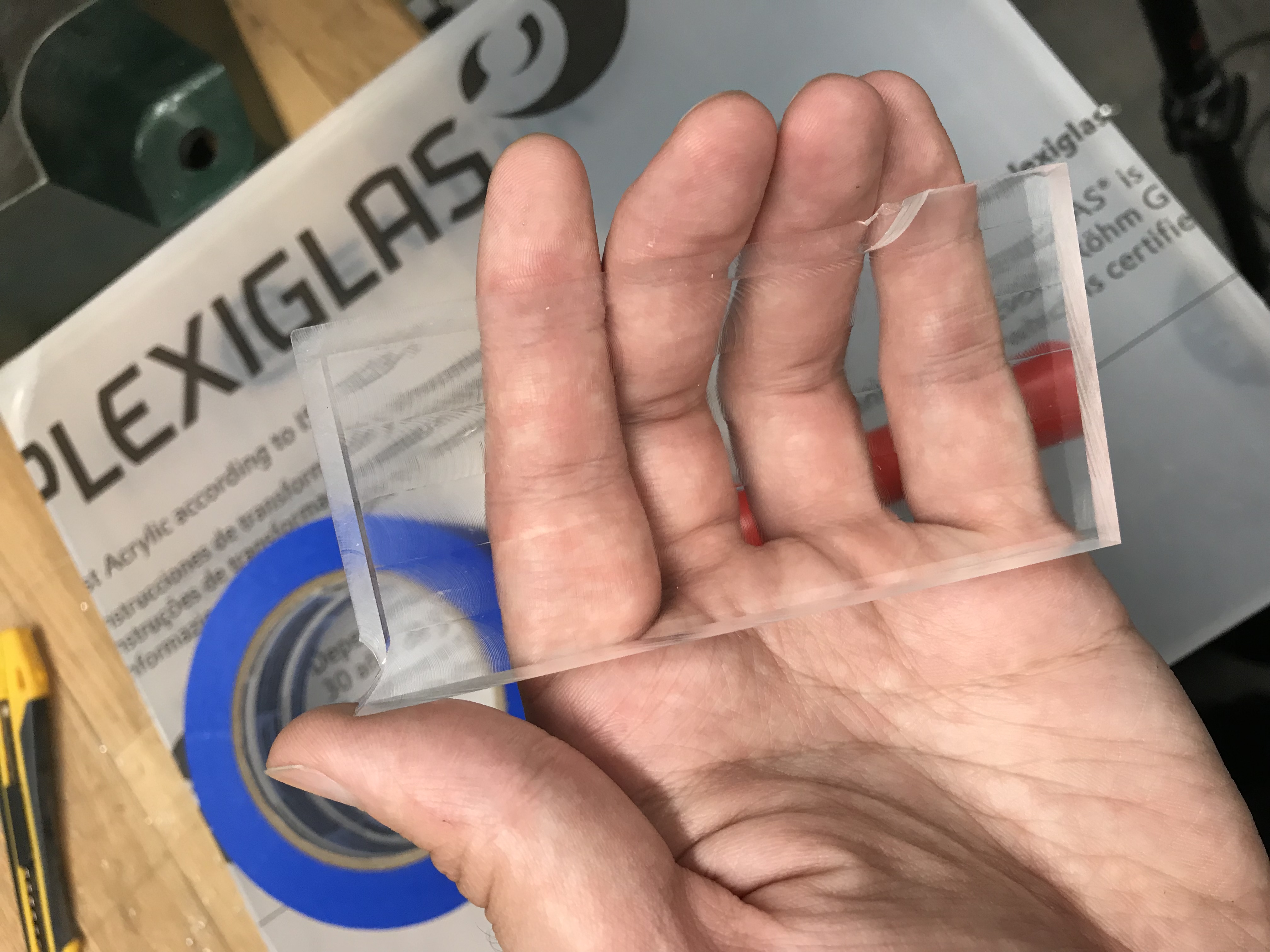
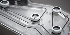
It's one thing to design the part, another to sit down and make it. In CAD you have the advantage of everything being ideal: 10mm plastic is indeed 10mm thick without fail. However, the real world doesn't enjoy working like that, especially producers of acrylic it seems. Since the GPU o-rings are very small, I was worried that if I happened to get a particularly naff bit of acrylic there could be issues with uneven pressure along the seals. To mitigate this, I simply ran a facing op along the surface using a polished acrylic radius face mill. Not only does this flatten the surface nicely (assuming the bed was flat...) but the finish from these cutters is fantastic. I was quite worried that after facing there would be noticeable machining marks that would throw the appearance.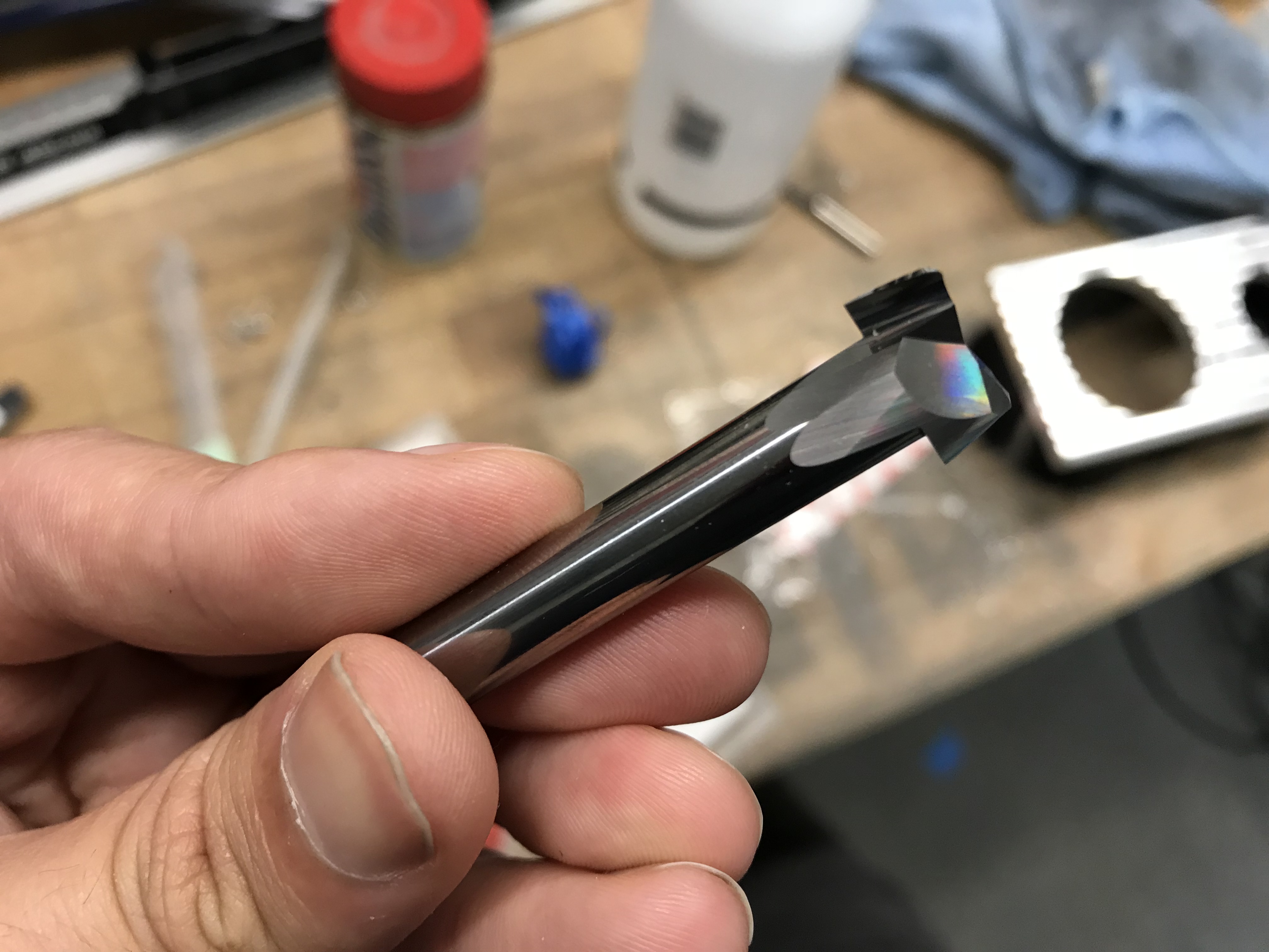
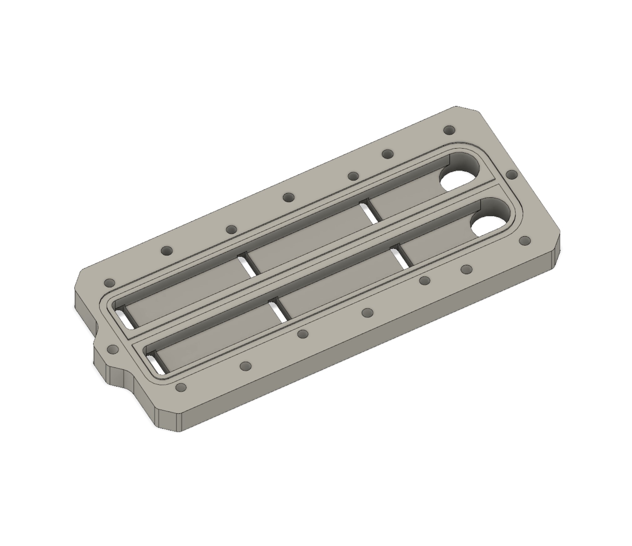
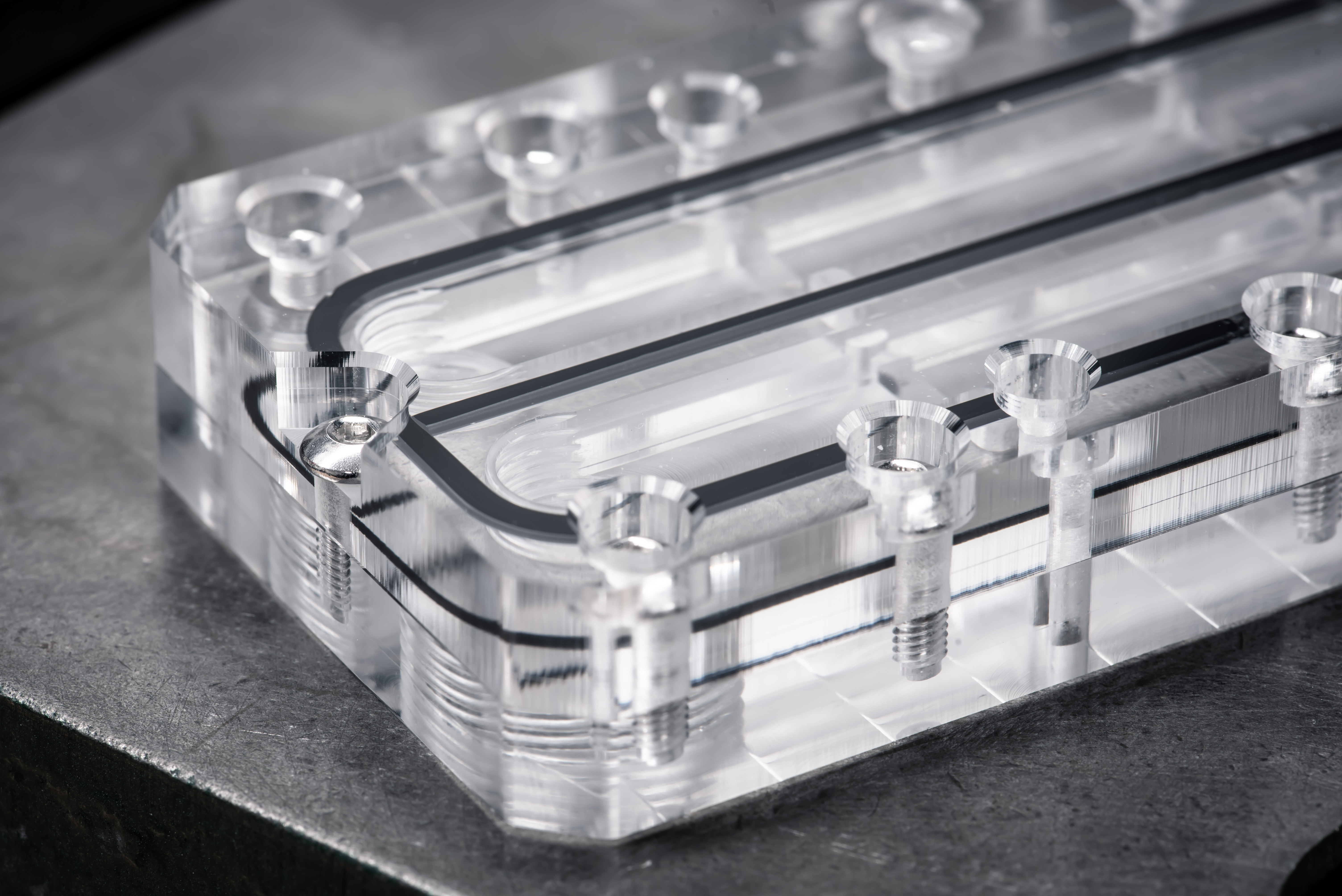
As with the larger blocks, I went with a 2mm o-ring for the interior sections, for this I used a 2.2mm-wide channel cut to a depth of ~1.3mm. The double-sided OPs were handled via the super glue method and located with pins. Tooling wise, I tried to keep things simple, using the 14mm polished edge radius mill for facing, followed by a 2mm single flute for the o-ring channels. The main channels were roughed with a 6mm single flute and then finished with a 4mm polished edge single flute (the top corners are a 2mm radius, so I couldn't use the 6mm). Thread milling was handled with a 2mm Datron thread mill cutter along with a Whitworth 6mm thread mill for the G1/4" ports.
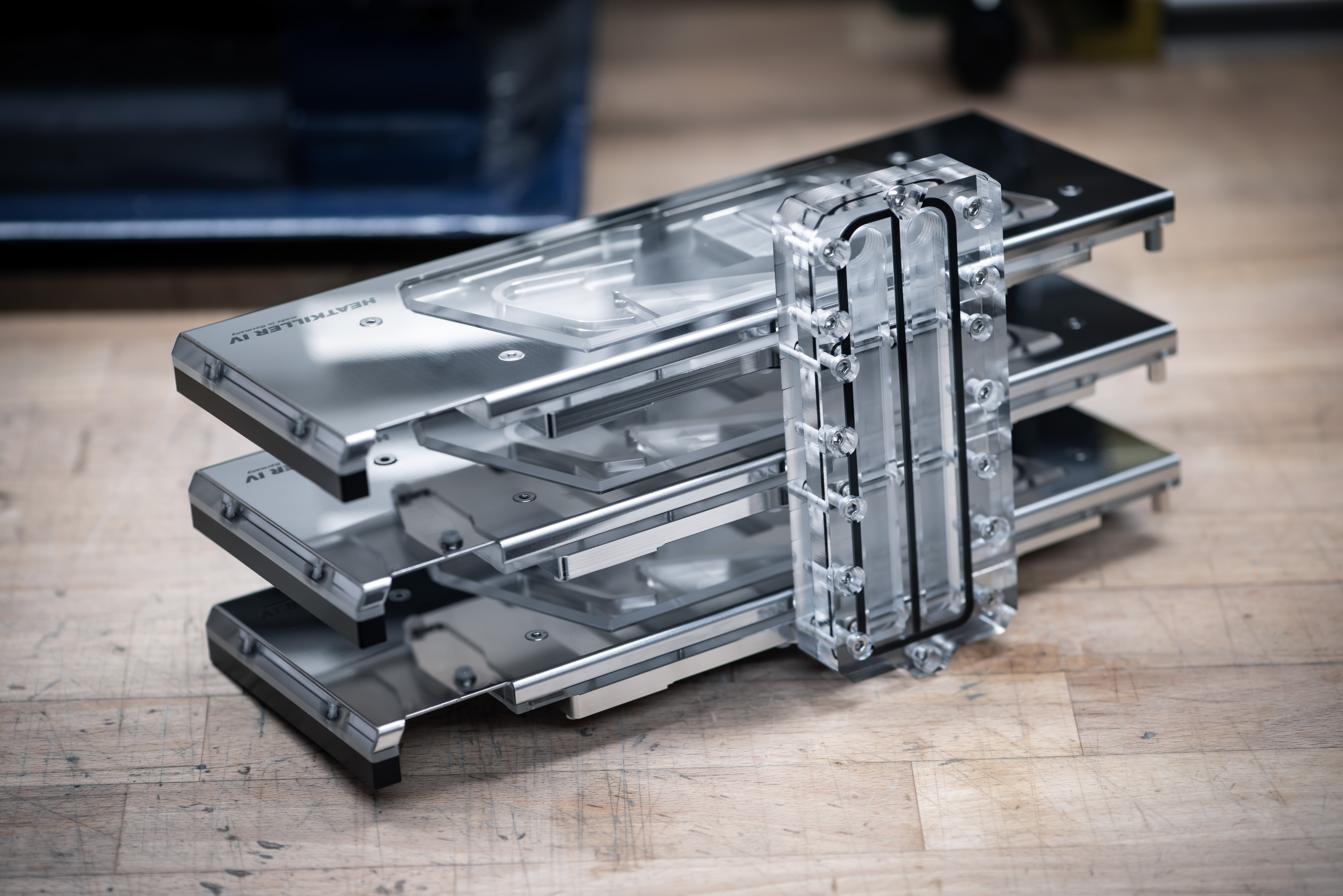
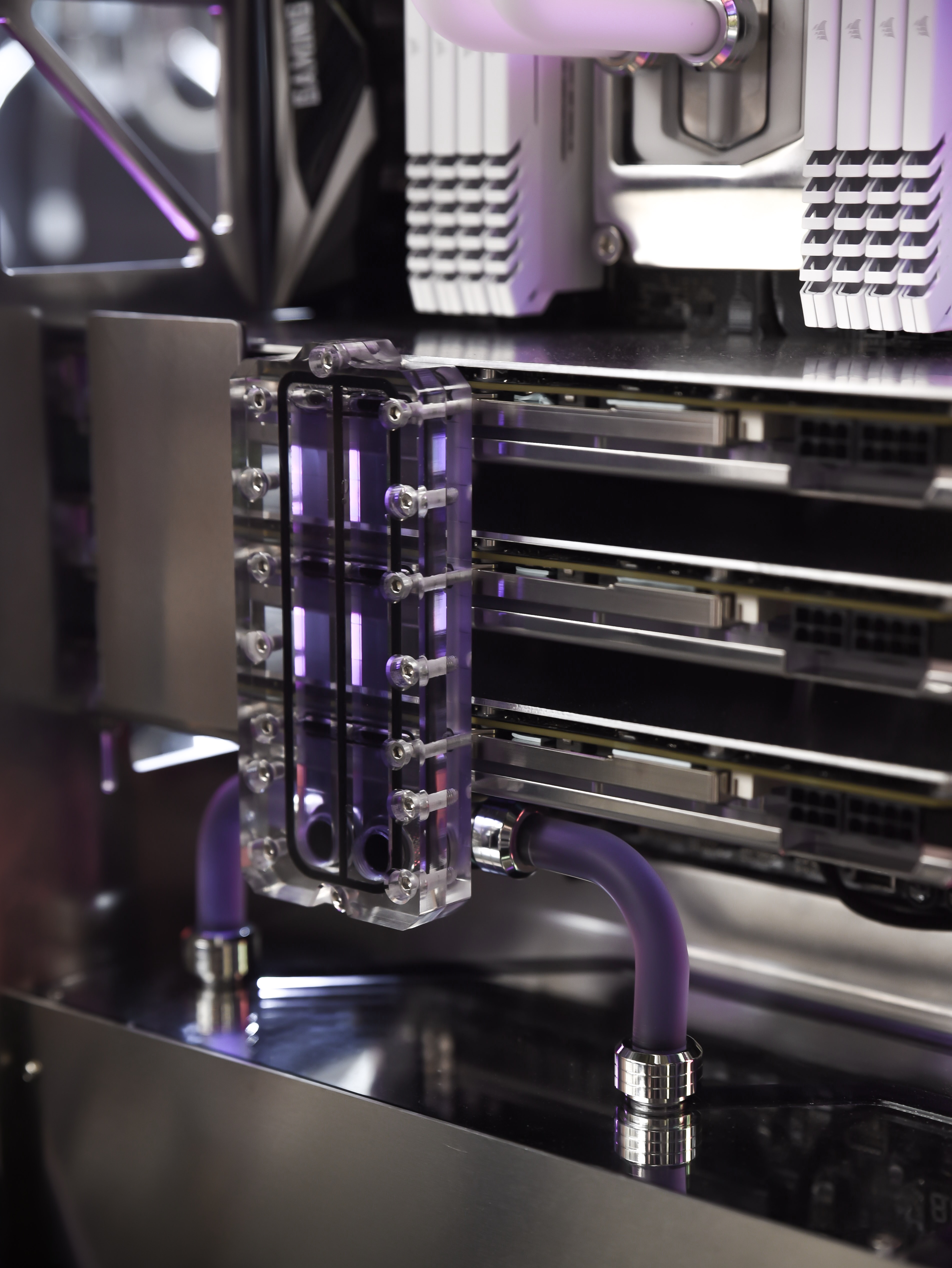
Et voila! The initial filling of this loop proved a success, and the purple fluid comes through the clear acrylic nicely. Be sure to check out the 1000D Mega-Build playlist on our YouTube channel, or if you prefer the write-ups you can see all the coverage of this build across the site using this link.
RELATED ARTICLES


MSI MPG Velox 100R Chassis Review
October 14 2021 | 15:04

Want to comment? Please log in.