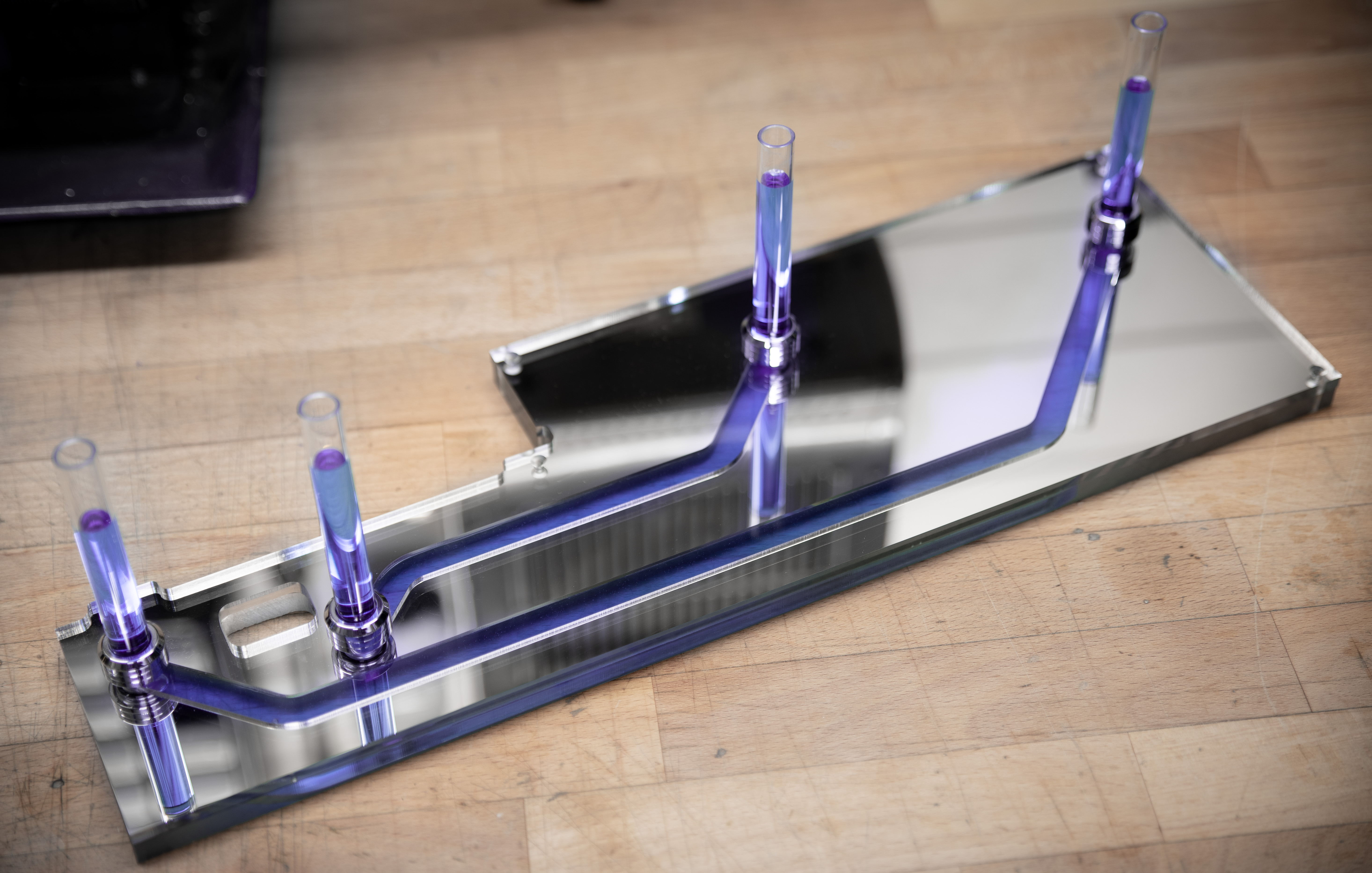
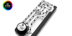
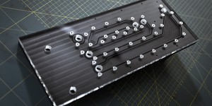
If you kept up at all with our monstrous 1000D mega-build, you will know that it sports a rather large number of water-cooling distro plates i.e. CNC-machined panels that take the place of tubing to route coolant around the PC. I've previously gone into some of the process around these plates in features on How to Integrate Tube Reservoirs and Making a Custom SLI Terminal, but that's mainly been from the perspective of somebody who's made one before.
In this article I wanted to help show the process behind designing a distro plate of your own, as ever there's also an accompanying video so you can see it all in action. I thoroughly recommend watching it if you're interested in the subject as details can sometimes get a bit muddy in text form. I also want to clear up some of the misconceptions that are commonly thrown around regarding these plates, namely that it's the reserve of professional modders and/or machine operators. So let's hop to it!
It's all about the CAD
This article is about designing the plates, rather than making them. The field of manufacturing is pretty vast and things vary a lot from machine to machine, so it makes sense to divide the two topics to make them more manageable. If you're able to design a plate to begin with, then you'll have the ability either to manufacture it yourself, or pass the files on to somebody else who's capable of doing it on your behalf.

To start, that means using CAD software. I'm going to be using Fusion 360 from Autodesk, it has a great feature set and also has the bonus of being free for educational, hobbyist and small business use. Don't be fooled by their insistence on trial copies and so on, it is indeed free to use unless you're generating above a certain threshold from use of the software. The big advantage for folks like me is that Fusion has both the CAD and CAM (needed for machining the plates) environments in one place along with other tools that supplement the modelling of parts. There are also buckets of tutorials for it online, so it's usually fairly straightforward to figure out how to use a particular function.
Of course much of this will be applicable to other software packages too.
Let's get stuck in
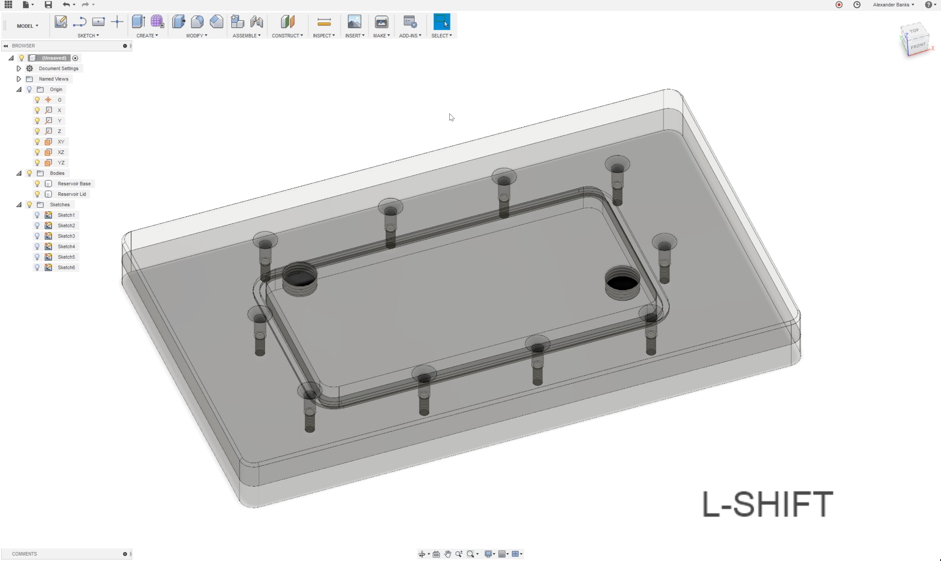
Let's go with a simple model, a rectangular reservoir with an in and out port. This uses all of the same principles you'll need for modelling a distro plate, I'll cover things like channel depths, hole spacing, feature offsets as well as throw in a few handy tips to make the process simpler and more robust.
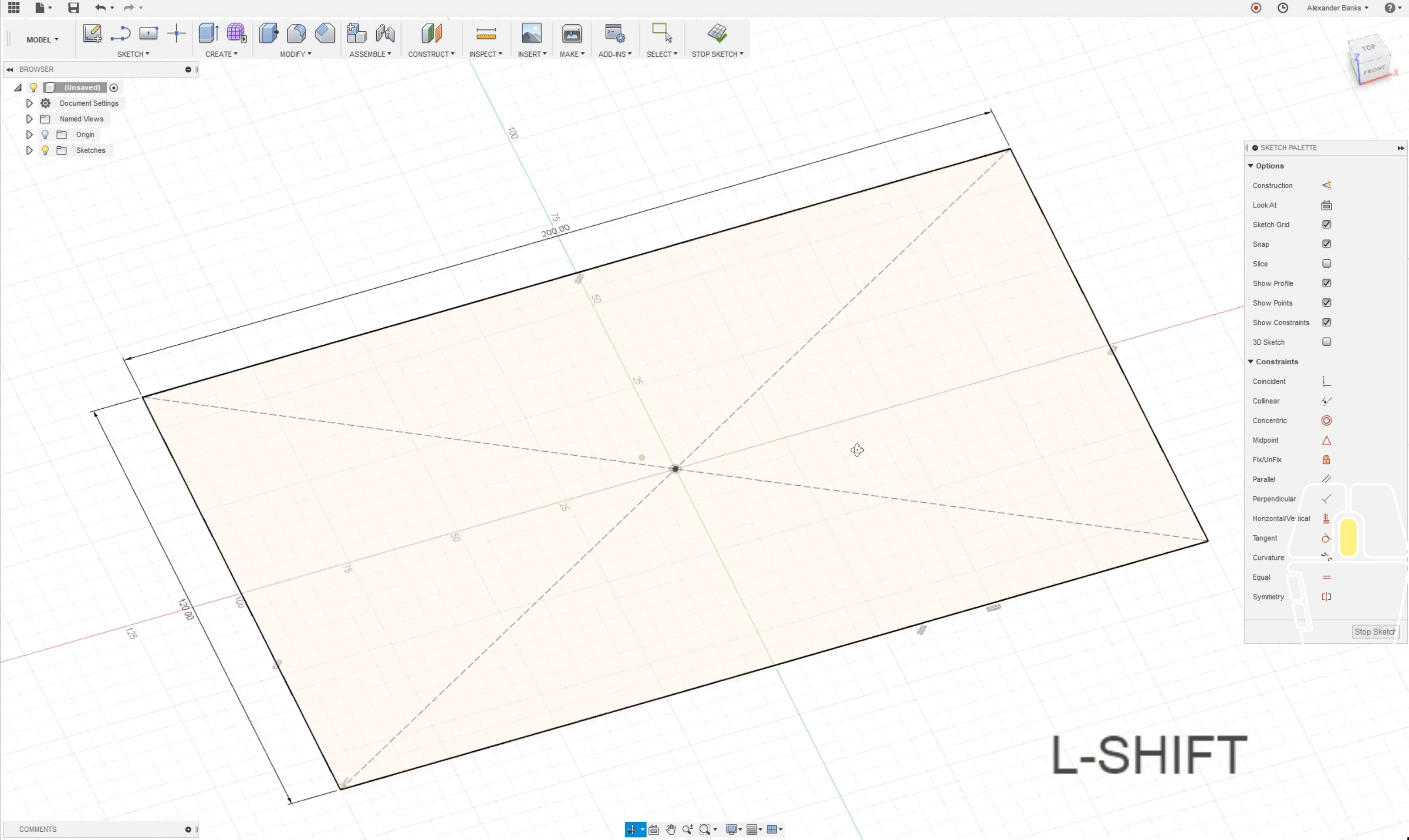
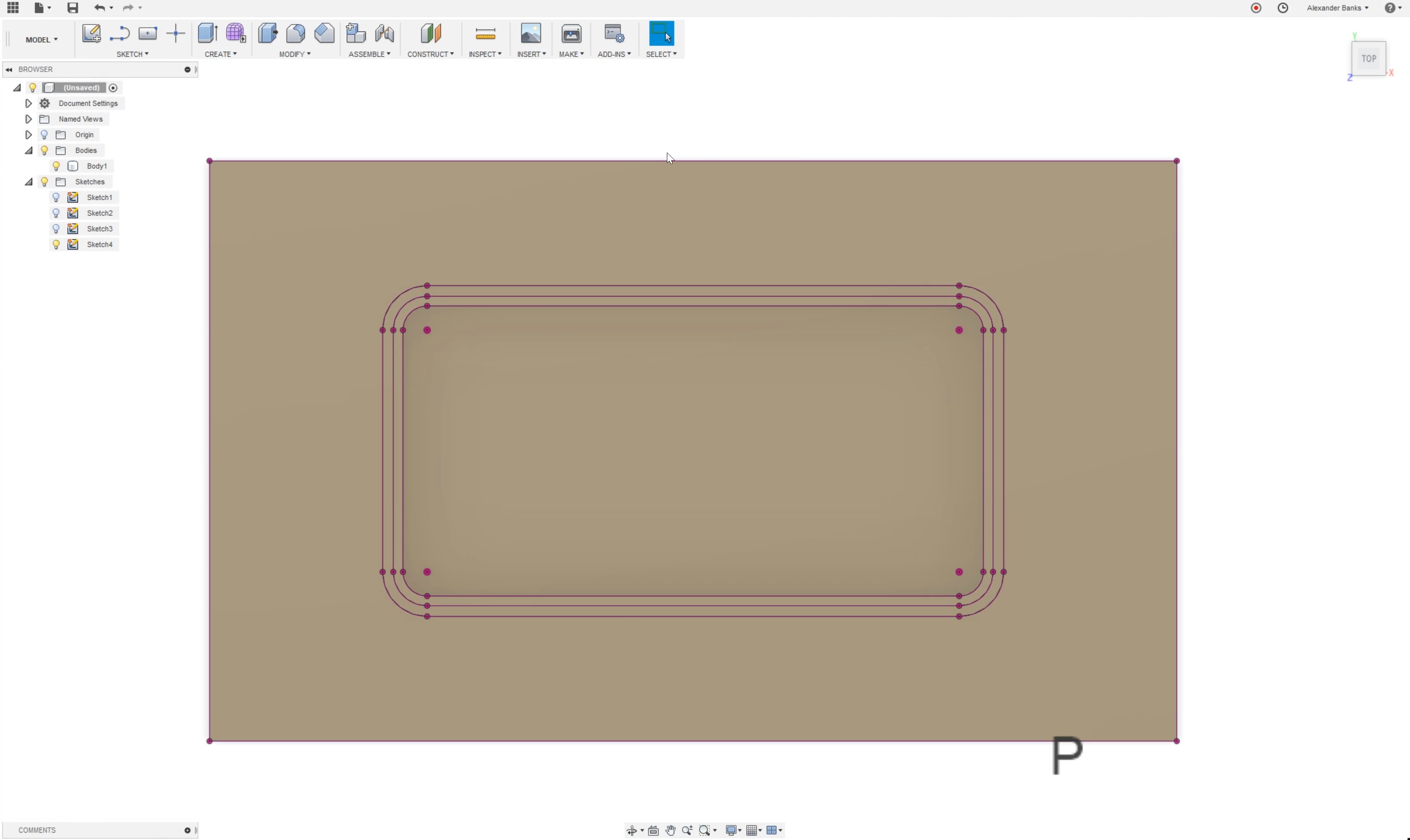
To begin with though, we need a sketch. If you've never used CAD before, then I suggest going through some beginner tutorials just to get comfortable with the layout and terminology. Open a new design and click 'New Sketch', then choose the 'Centre Rectangle Tool' (I use it a lot so have it pinned, you can normally find it in the drop down 'Sketch' menu). The reason for using 'Centre Rectangle' is that it's then easy to work with the origin and axes found in the sketch environment, using these is a good idea as it makes doing operations such as circular patterns, rotations or mirrors much easier. Our reservoir is going to be 120x200mm in size, either type those numbers in when drawing the rectangle or use the 'Dimension Tool' to assign them, after that click 'Stop Sketch'.
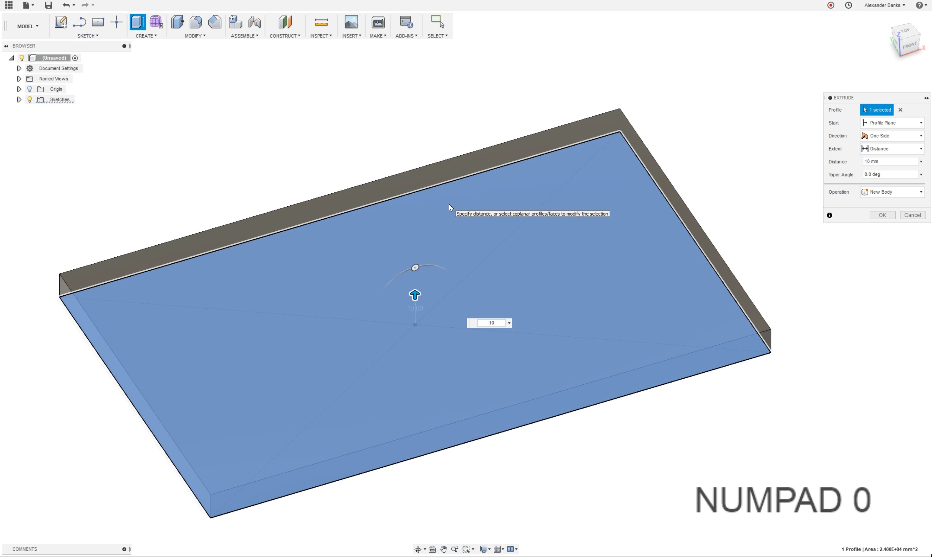
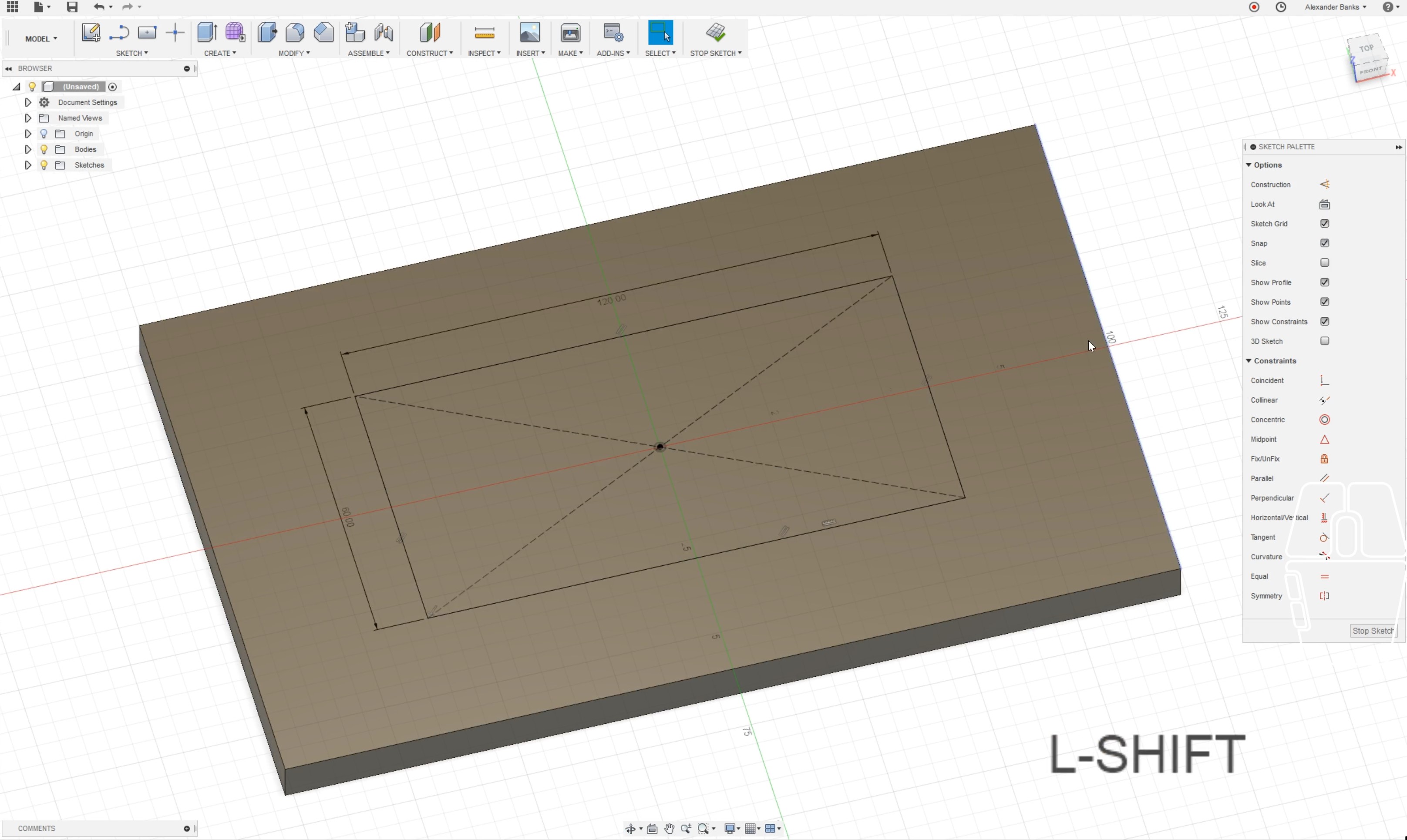
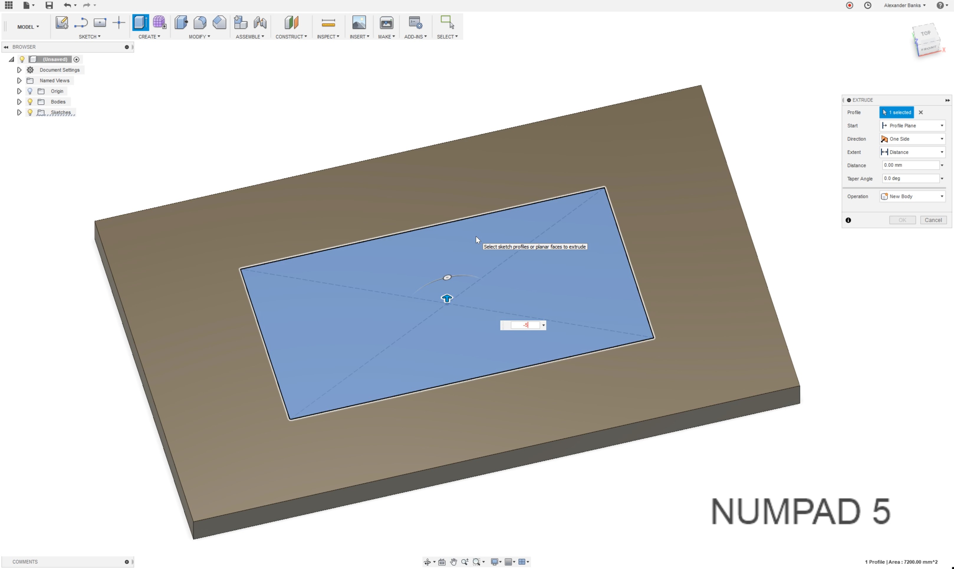
Now that we have a flat rectangle, it's time to make it 3D. Using the 'Extrude' tool, select the rectangle and type in a value, this will be the thickness of the piece of acrylic (or other material) that you wish to use, I like to use 10mm plates. Now that we have a thick piece of material, it's time to cut out the first channel. Click 'New Sketch' and select the top face of the cuboid, this creates a sketch on the top surface. Again using 'Centre Rectangle' draw a 60x120mm rectangle from the origin of the workpiece and then 'Stop Sketch'. Using the 'Extrude' command, select the rectangle we just drew, but this time we want to cut, so type a negative value such as -5 into the box. Fusion will automatically adjust things so that it cuts away material, however you can change this manually too in the dialog box.
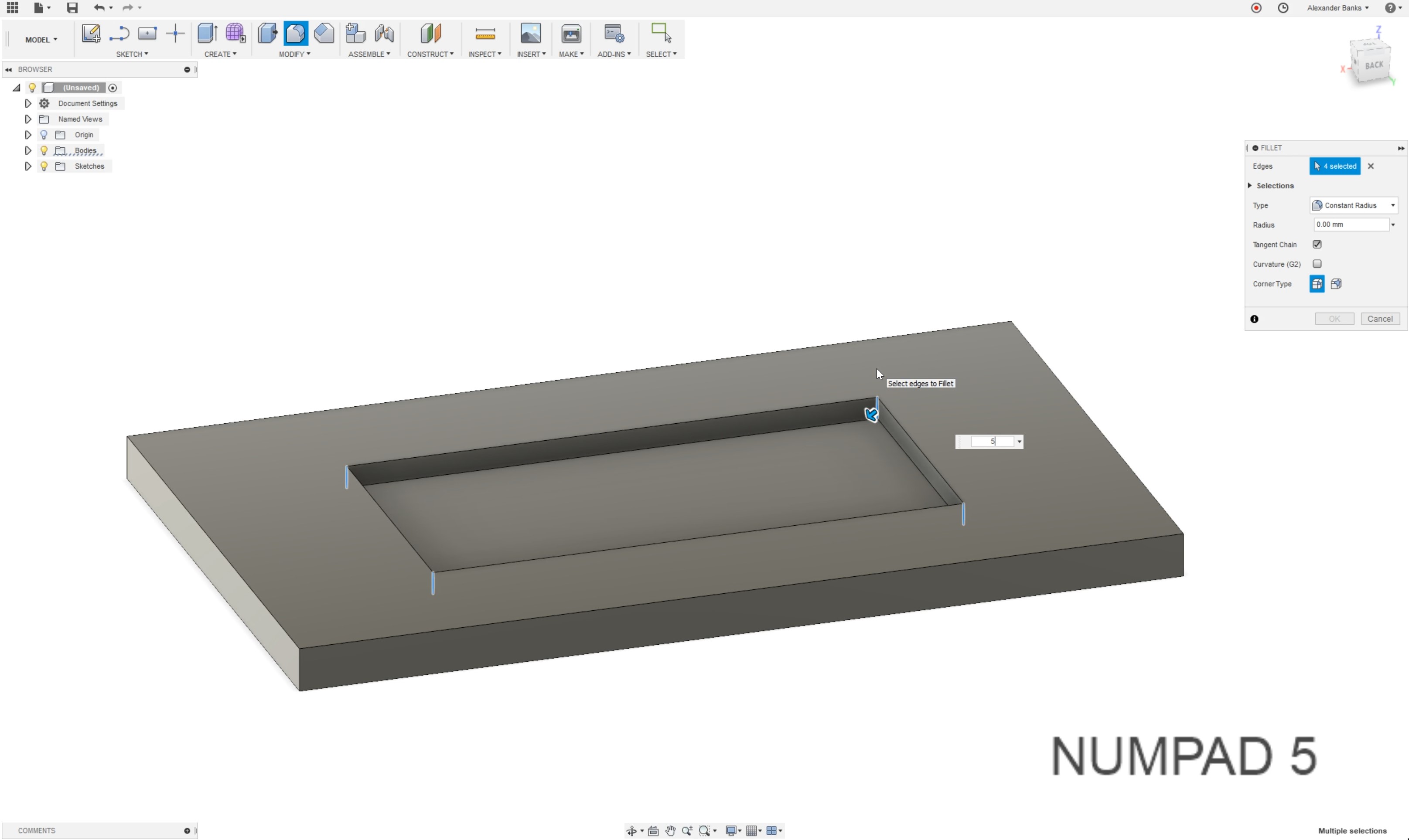
Since we've hollowed out a portion of the plate, let's round the internal corners a bit. If you're going to have a piece CNC-cut, it won't be possible to get completely sharp internal corners, the sharper the corner, the smaller the endmill will need to be. A handy tip is designing a plate around the largest possible size of endmill that can be used, a larger endmill will usually result in faster machining and often a better surface finish too, they also have the ability to cut deeper than smaller diameter cutters thanks to greater rigidity. Using the 'Fillet' tool, select the corners and type in '5' to the dialog box, this will apply a 5mm fillet to the corners. It's possible to do this in the sketch environment too, but you gain more flexibility using the feature tool instead.
It's now time to make the O-ring channel, this will seal the reservoir making it watertight. Naturally it's important that it's the correct width and depth, there's a handy way of ensuring this. Make a new sketch on the top surface again, we're going to use the 'Offset' tool this time to create the channel. Click 'Offset' in the sketch menu (or press 'O') and then select the edge of the rounded rectangle cut-out, then drag out the line a bit. The tool follows the geometry and draws a line offset by a value, since we want a gap between the o-ring and the reservoir, type in 1.5mm. This places the line and even 1.5mm around the edge, I find 1.5-2mm works well for this, thinner than that and you run the risk of cracking the edge when the plates are compressed. Repeat this operation only this time type '1.5 + 2.2', now obviously you could just type 3.7 for this but typing the sum means you can easily double check things later. If you want to get fancier, you can click the little dimension label on the offset and type '+2.2', doing this will place the outer line 2.2mm from the inner line no matter where it is, it will change with the sketch.
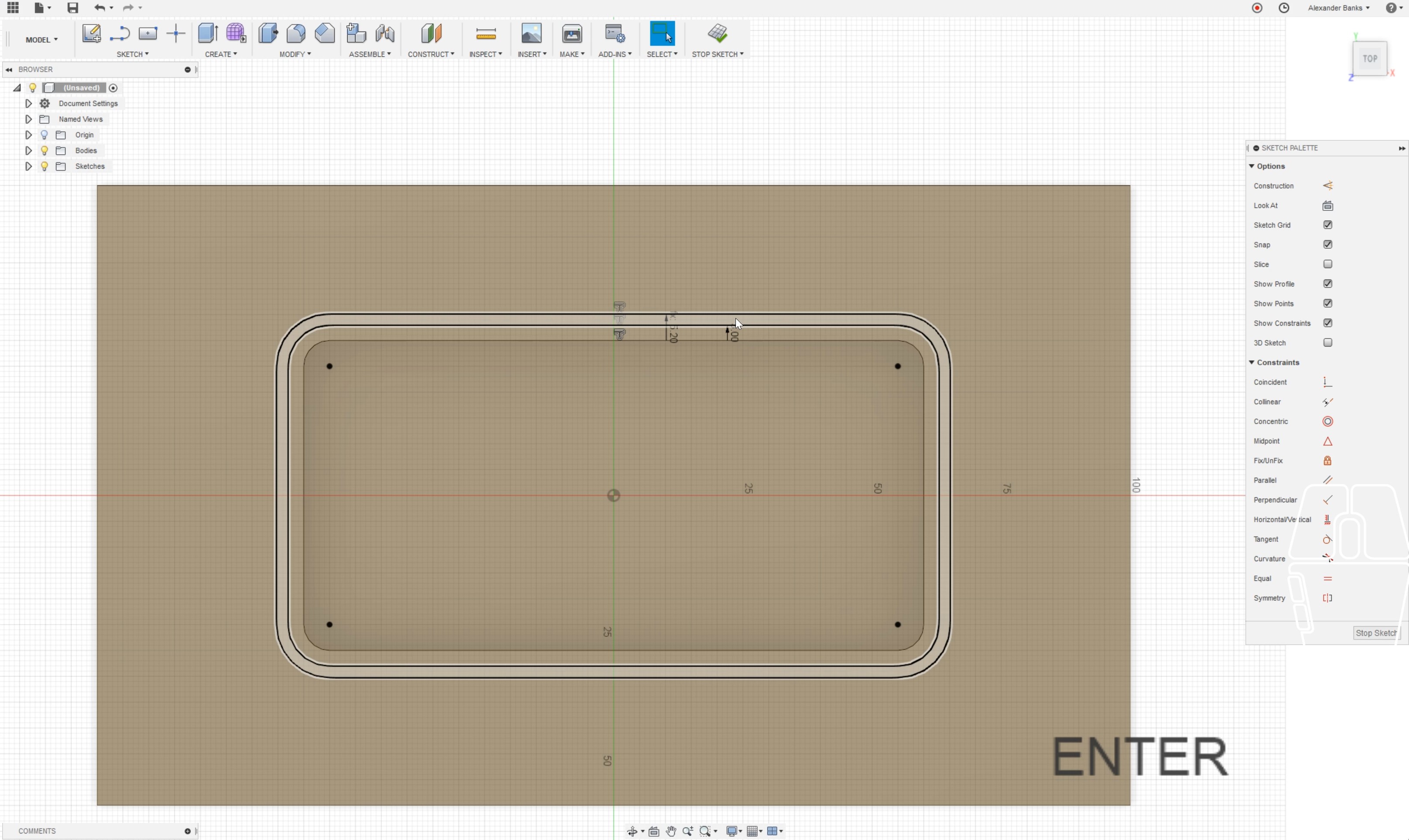
Why 2.2mm? I like to use 2mm o-rings for most of my work, I find they strike a good balance between being easy to use and also fairly compact. 1-1.5mm can be difficult to use on uneven material like acrylic, you also need tiny cutters for it, larger than 2mm works fine too but can look a bit fat. A 2.2mm channel will allow the o-ring to sit comfortably and compress evenly, providing a good seal. To do that, we need to extrude the channel we've just drawn down 1.3mm, the O-ring will now have a neat channel to sit in. To reiterate, that's a channel width of 2.2mm, channel depth of 1.3mm and offset from the deep cuts by 1.5mm.
The next step I like to make is begin work on the opposite half of the reservoir. Fusion has the ability to create separate parts within one file that even share operations, which makes plates like this very simple, it's also the reason why I haven't added screw holes yet, we'll get to that in a minute. To make the second half, create another new sketch on the top surface, in this sketch use the 'Project Geometry' command and select all the available lines. Then using 'Extrude' again, select all the shapes on that sketch, only this time in the dialog box, make sure that 'New Body' is selected where it normally says 'Join' or 'Cut', as before type 10mm and click okay. By selecting 'New Body', Fusion has created a new object that can now be treated separately to the one we were working on earlier.
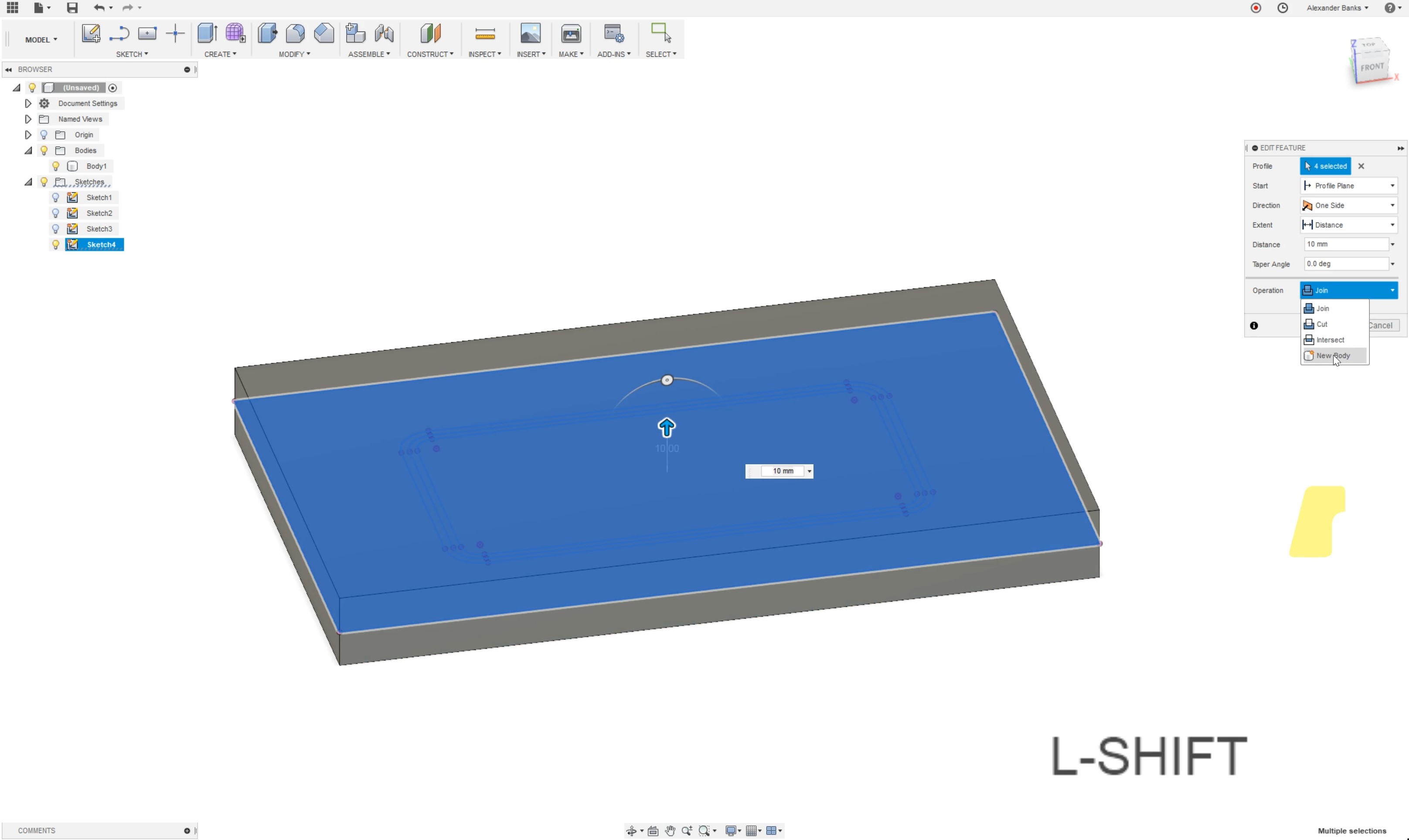
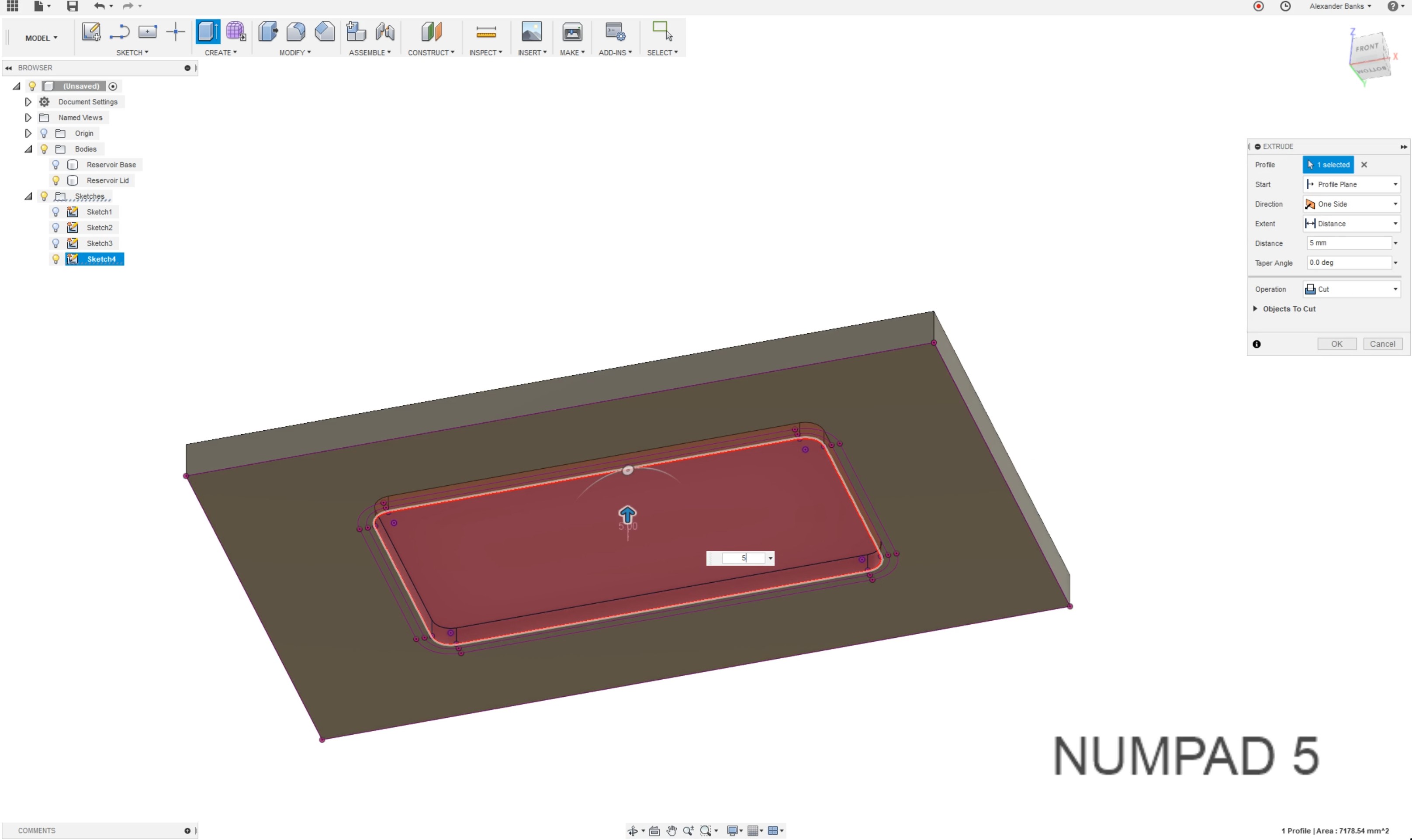
Toggle the visibility of the bottom plate by clicking the lightbulb icon in the top left, then also toggle the visibility of the sketch we just drew (since it defaults to off once it's been used in a feature). We can now extrude the centre piece again, but this time we're going up, so type 5mm and double check in the dialog box that it says 'Cut'. We now have two halves but nothing to hold them together, so it's time to add the screw holes.
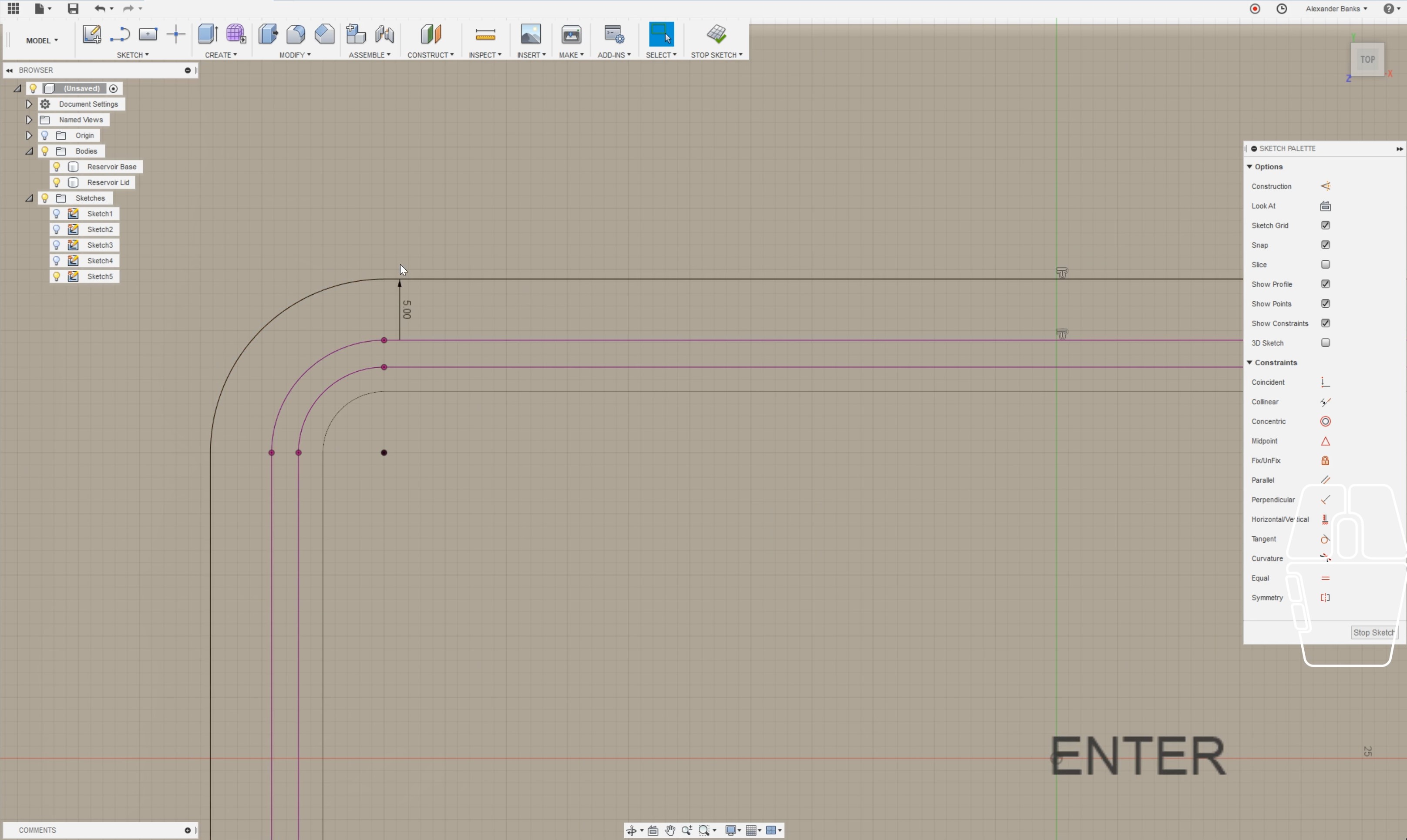
To ensure that the screw holes are evenly placed around the reservoir, we're going to use a pattern and path to place them automatically. For a small reservoir with a simple shape like this it isn't that important, but if you have a big plate with maybe 150+ screws and all sorts of funky shapes, this method is a life saver compared with placing them manually. To do this we need to use our friend the offset tool again. Create a new sketch on the top surface of the second plate, then toggle visibility so that the bottom plate with the O-ring channel is visible. Use 'Project Geometry' to project the O-ring channel into the sketch, then toggle visibility back on for the top plate. Using the 'Offset Tool' select the outer line we just projected, then type 5mm to create a line that's evenly 5mm from the channel. The screws will go along this line, so they need to be away from the channel a little.
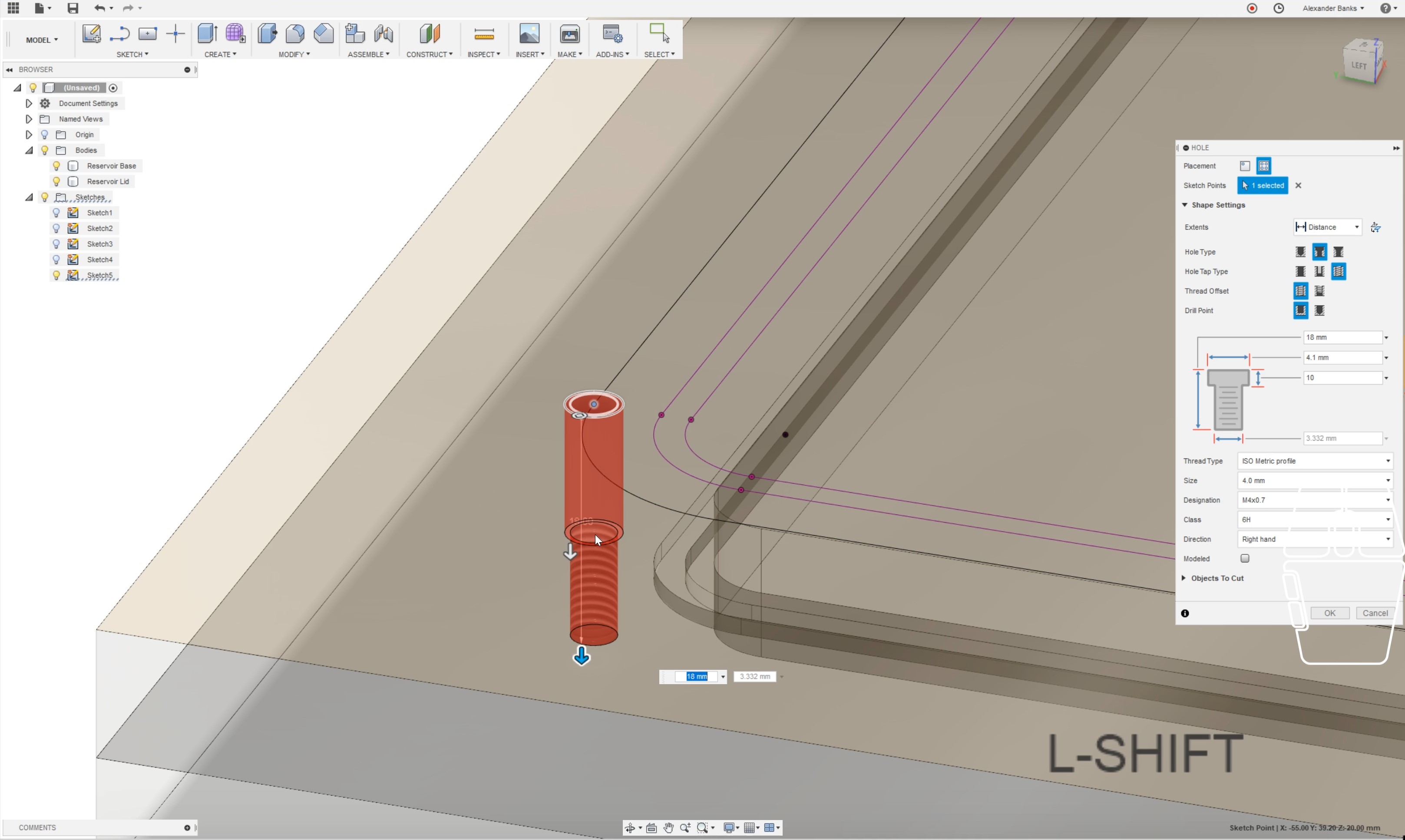
We're now going to make use of a particularly useful CAD package feature, the 'Hole Tool', rather than drawing circles manually, this tool can create complex holes for us, which is both a time saver and also provides some very handy options. Under the 'Create' tab, click 'Hole' then choose a point on the offset line we just drew, I usually pick a point where a line goes into an arc or a corner. In the dialog box, choose 'Counter Bore' for 'Hole Type', 'Threaded' for 'Hole Tap Type' and 'Flat' for 'Drill Point'. These characteristics determine the shape of the hole that will be made, I'll explain why I chose these in a minute. Make the counterbore width 4.1mm and the depth 10mm, under the thread size choose M4x0.7, make the total hole depth 18mm. The reason for these options is that with one operation we've now created two separate holes. The top plate has a 4.1mm clearance hole thanks to the counterbore, the bottom plate has M4 threads to a depth of 8mm, neat huh? Click okay, if you wish to add a countersink for low profile screws, use the 'Chamfer Tool' and select the top edge of the hole, 2.1mm works well I find as it guarantees the screw heads sit just below the surface.
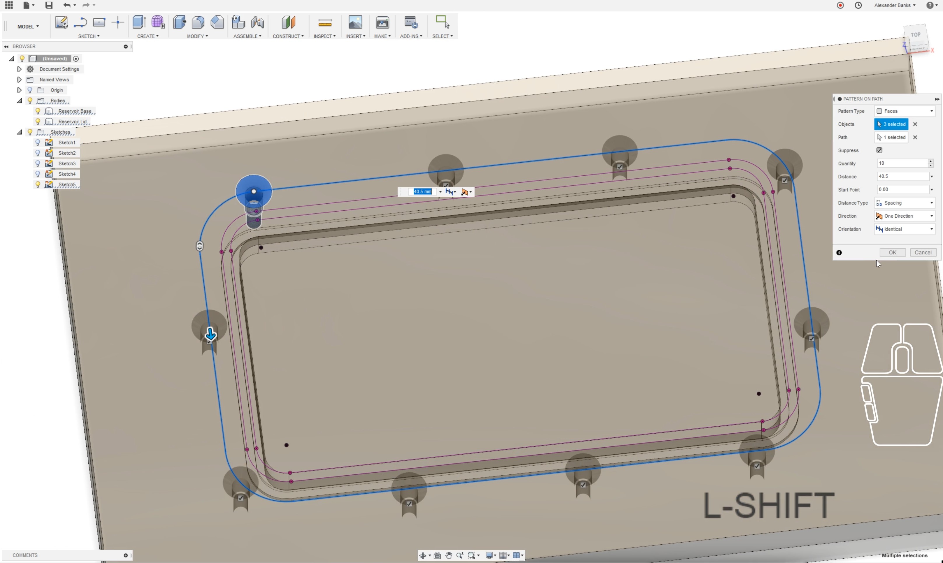
Thing is, we have only one screw hole currently. To copy them along the path, choose 'Create -> Pattern along path', select the hole we just made (and countersink if you added it), then under where it says path, choose the path we drew earlier (you may need to toggle visibility again). Where it says "Extent" I prefer to change to "Spacing", extent will divide the length of the path by the number of iterations, which makes screw placement completely even, but at the cost of a little flexibility I find, it can also be a bit slow when working with lots and lots of screws and long paths. Under 'Distance' type 40.5mm and make 'Quantity' 10, I like to space my screws between 35mm and 40mm generally (although a little over 40mm is of course fine), having more screws means less pressure is exerted on each thread, worth considering with acrylic blocks that can crack if you over exert them. Conveniently you can also disable individual iterations, handy for more complex paths were screws may intersect with one another or be spaced too close together in loops.
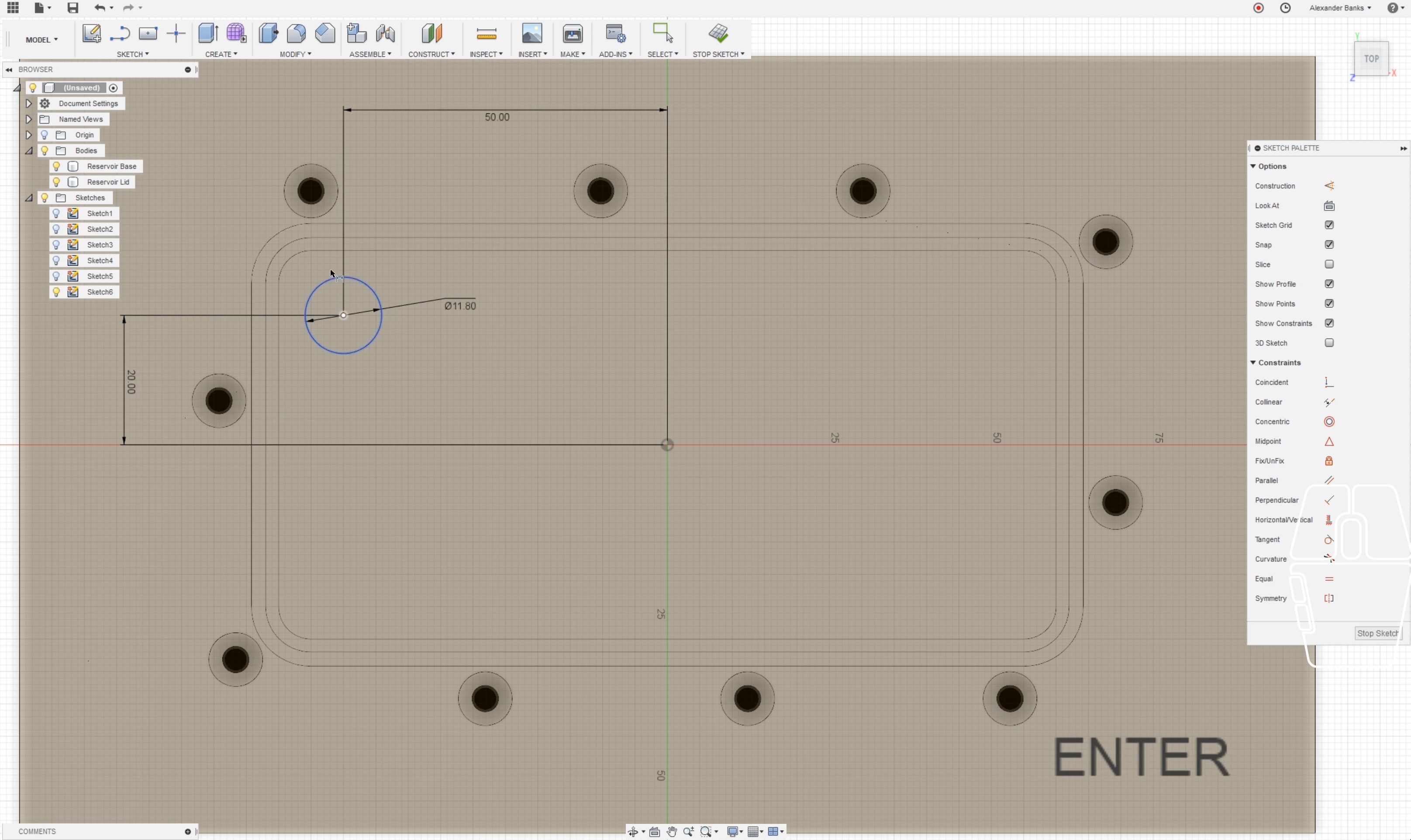
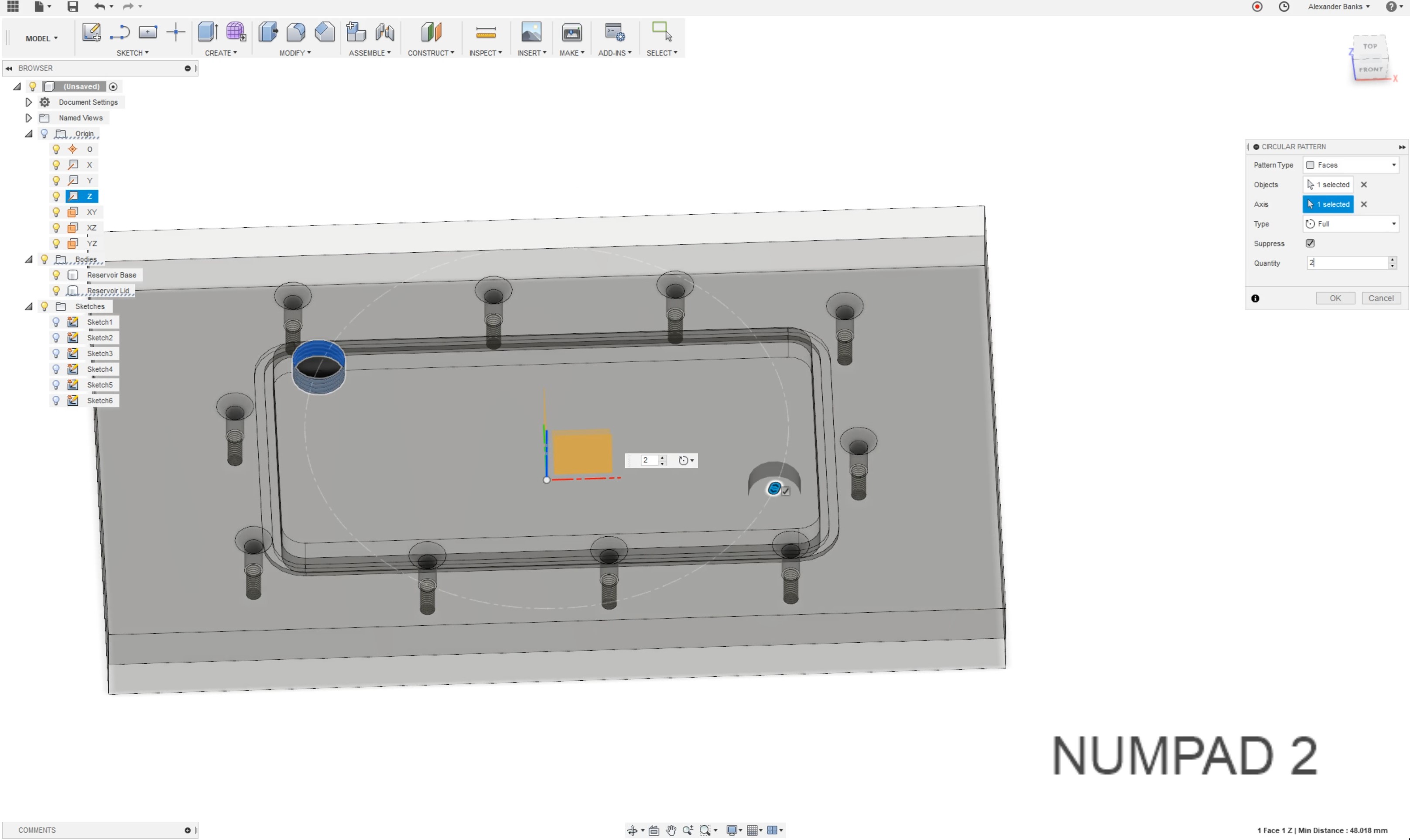
We're almost there! With the screws managed, it's time to add the ports. Create a new sketch on the top plate again, then choose a spot in the top left corner that's still above the cut section, using the circle tool, draw a circle 11.8mm in diameter, this is the size required to tap for a G1/4" port (although 11.5mm works fine too if doing yourself). You can use the 'Dimension' tool to position the hole accurately from the edges. Extrude the circle down into the plate 5mm, it should intersect the interior, we now have a port going into the reservoir. For the outflow, let's explore a trick I mentioned near the beginning and use the 'Circular Pattern' tool. Choose the tool from the 'Create' menu and select the hole we just made. For the axis we're going to use the Z axis, you'll find it under the the tab labelled 'Origin' above the 'Bodies' and 'Sketches' tabs. Change the quantity to 2 and ensure the type is still set to 'Full', this will pattern the hole around the Z axis, placing it in the bottom right corner.
Functionally we're now complete! If you wish you can add some aesthetic elements such as corner fillets and perhaps a chamfer to the top edge. These are all the techniques used for creating a distro plate itself. For channels, use the same methods but scaled down, I go into the techniques I use for linking routes between ports in the second part of the video (from 22:20 onward). For the channel widths themselves, I suggest 11.8-13mm, although you can use whichever size you prefer. I typically go with 11.8mm with a depth of 5-10mm (5mm on one side or both), you don't want to make the threads too short on ports since they require some strength and rigidity, I would suggest 4-5mm.
Now go forth and distro!


MSI MPG Velox 100R Chassis Review
October 14 2021 | 15:04

Want to comment? Please log in.