
Learning How To Design in CAD
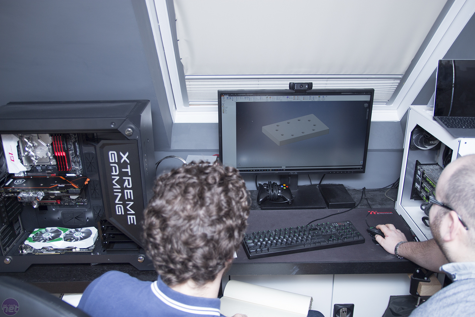
Alex uses a range of programs and tools for his drawings and renders. He chose Autodesk Inventor to go through things with me.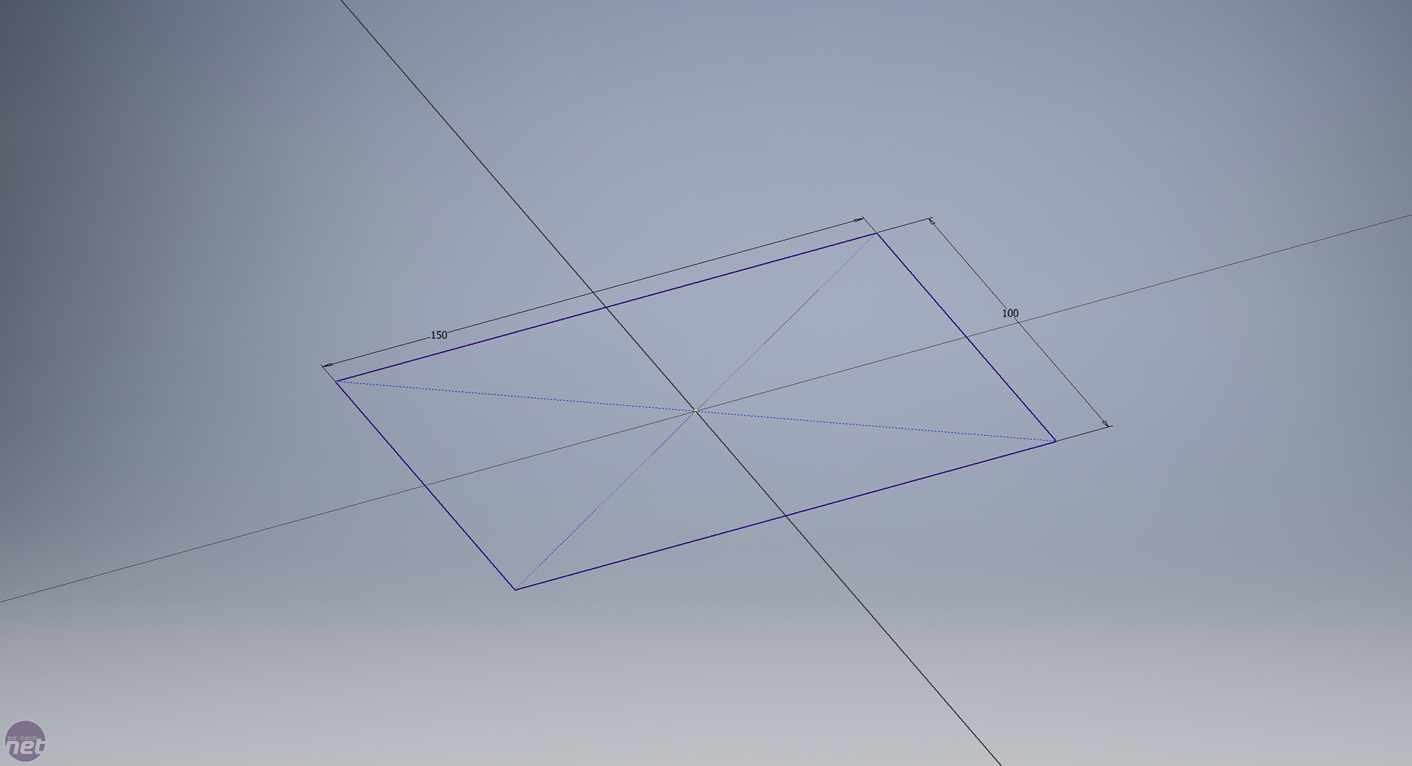
Click to enlarge
As with everything, the start of the drawing is very simple: Simply create a new project and start a 2D drawing. Draw the shape that you would like to use. We wanted a rectangular reservoir, so we used the rectangle tool and created this. The sizes don't have to be exact as these can be changed using the dimensions tool. The dimensions tool allows you to input values so that your creation will be the exact size you want. Once you have your drawing, you simply use the extrude tool to give it the 3rd dimension. We made ours 15mm deep.
Click to enlarge
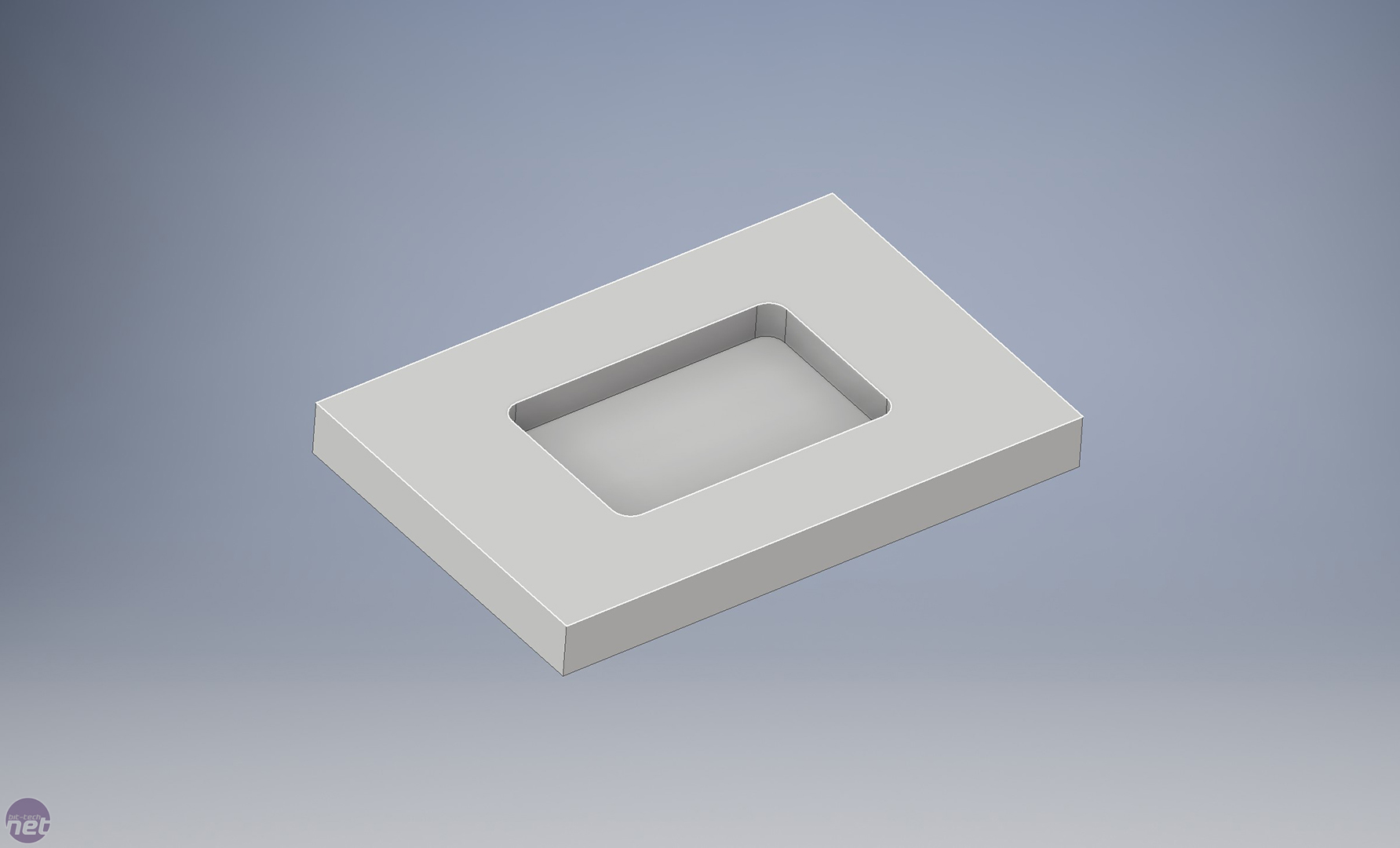
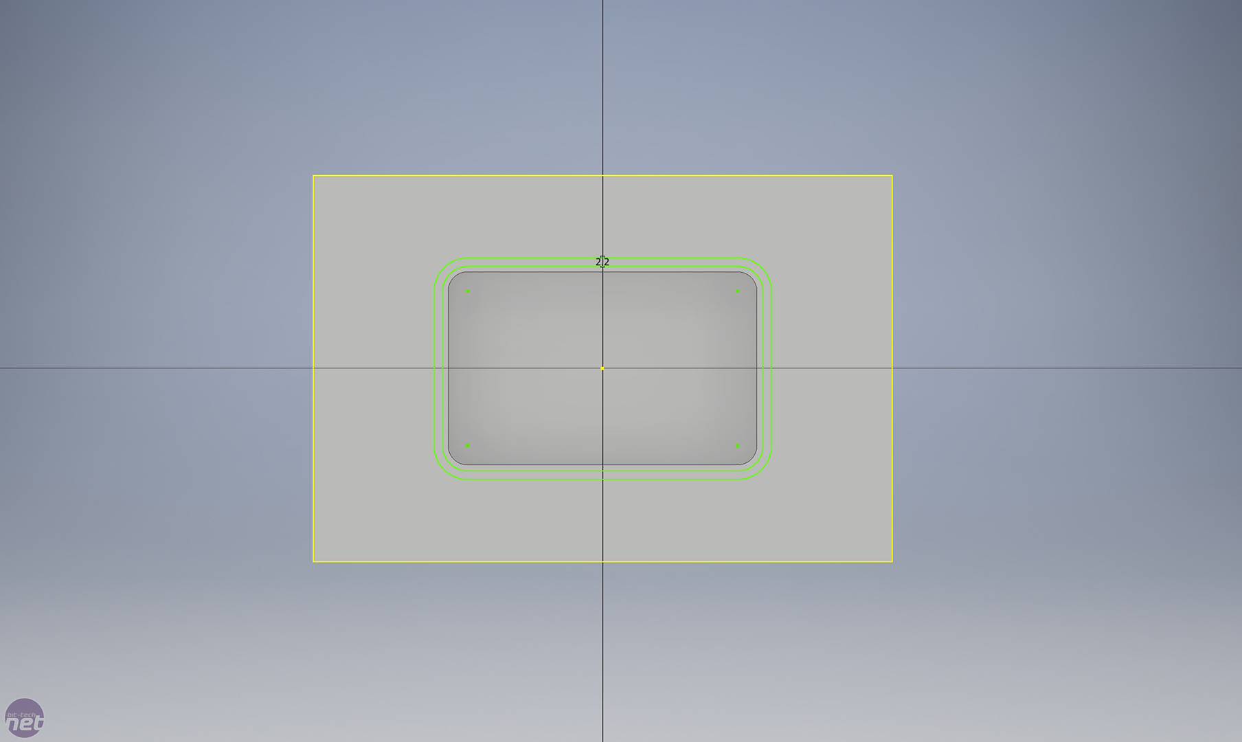
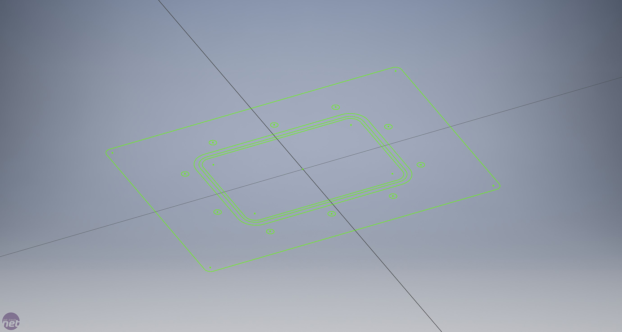
Now we need to make a smaller rectangle inside the larger one for the fluid to reside in. For this, we just draw a second rectangle onto the original drawing and again we extrude the shape. This time, we extrude down so that it creates an indentation. We used the fillet tool to create the nice rounded edges. Once this is done, we need to make an area for the O-ring/gasket. This is a little different; there is actually a tool that allows you to create offset shapes so that any line you make will be the perfect distance away from what you have previously drawn. We used this tool to create another two rectangles around our indentation (again with rounded edges). Once you have done this, you can just extrude the channel down. This makes a perfect little space for you to put an O-ring, which will ensure that the reservoir stays sealed.
Click to enlarge
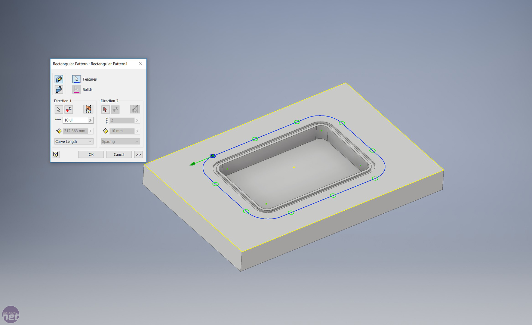
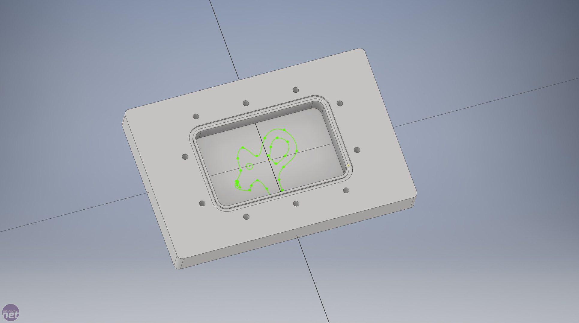
Once this is done, you'll want to put some holes in for the screws. One way to do this would be to draw each hole individually and then extrude down so that you have a hole to tap. Alex showed me another way, though, which works well. First, you create a construction line (this is a line used by other tools as an instruction line rather than a drawn line). You then place a circle on the construction line and create your extruded hole. After, you can use the rectangular pattern tool to repeat the holes around your shape. You can choose how many holes you would like and how far apart from each other they need to be. This is the first part of our reservoir completed. We drew a silly shape in the middle of it and extruded it up slightly, and this was for no other reason than for Alex to show me how to create shapes that can be seen through the reservoir.
Click to enlarge
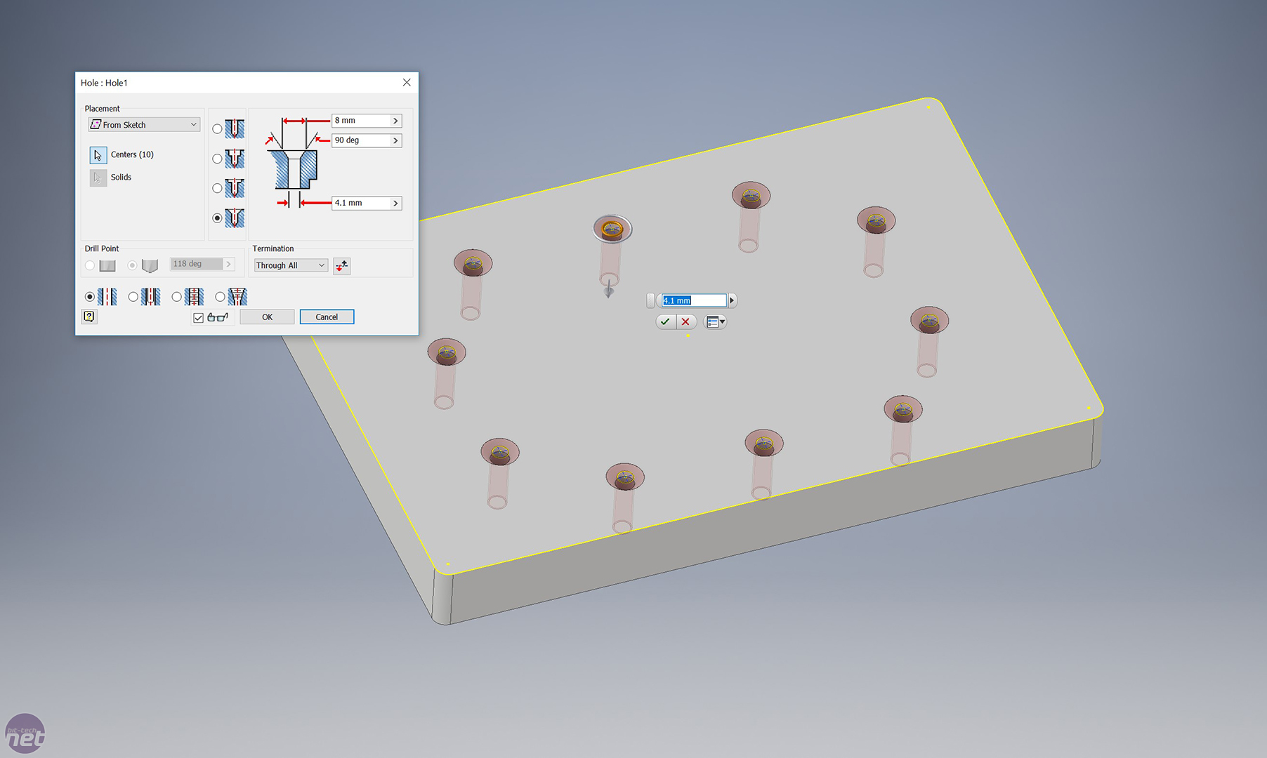
Now, we create a new sketch and copy the previous drawing we made over. We then use the hole tool to countersink the holes. This will ensure that when we put the two parts of the reservoir together, the screws will not be sticking out. You also want to add in inlet and outlet ports to this part.
Click to enlarge
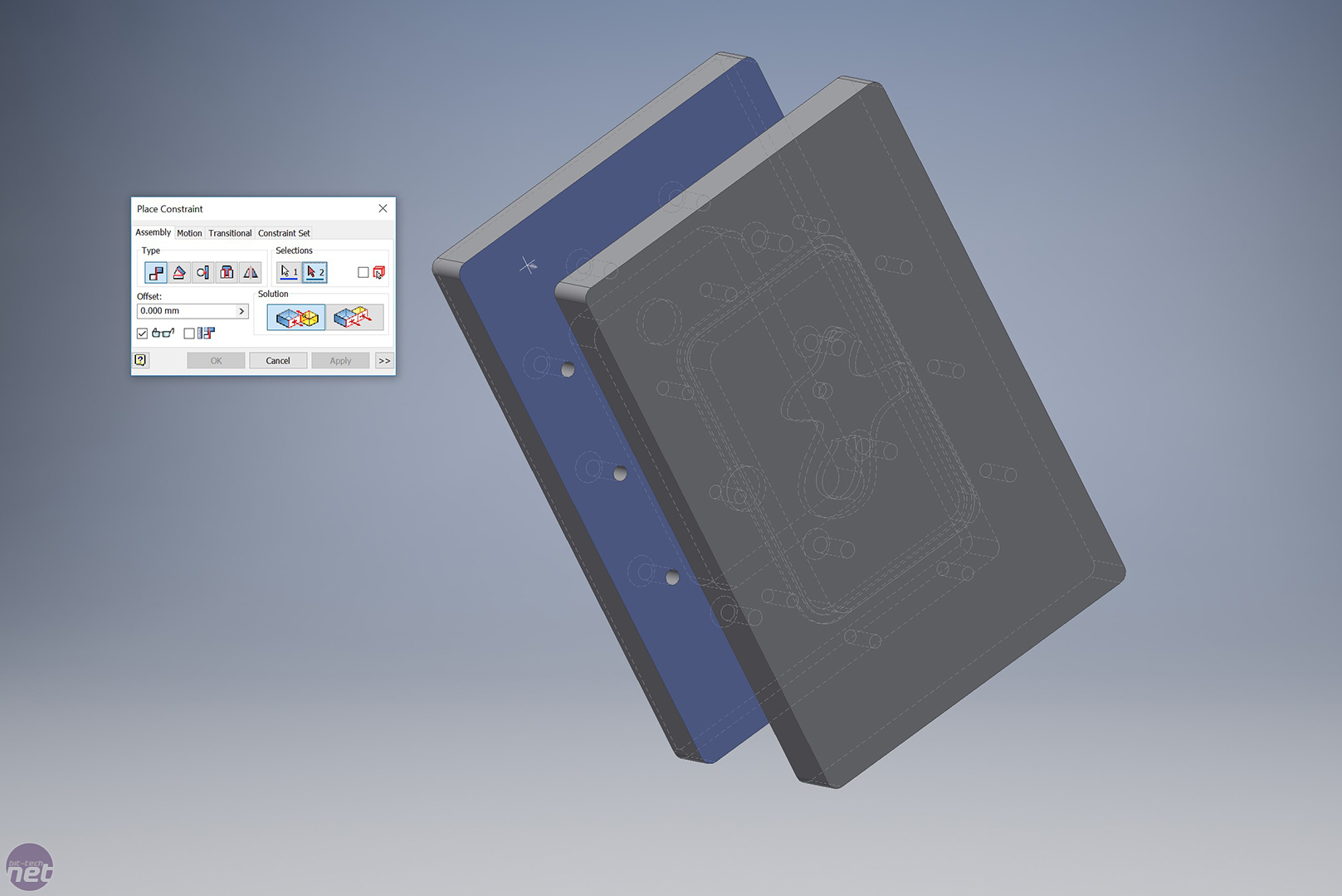
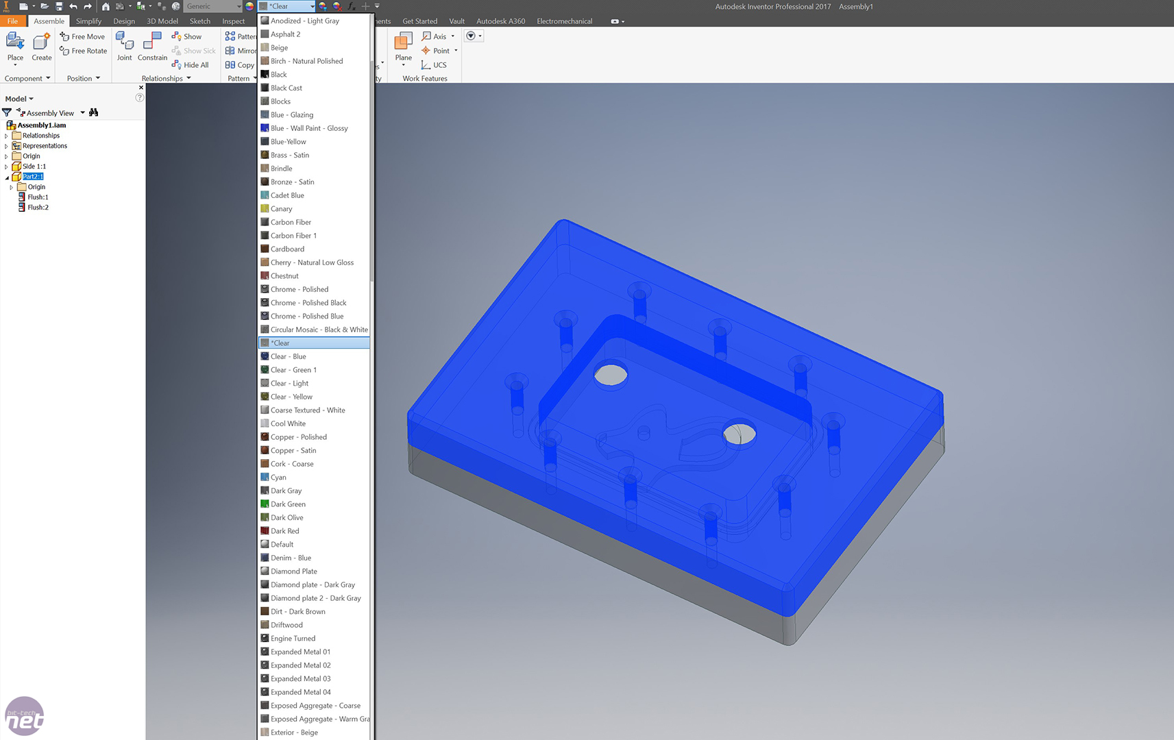
Once both parts are made, it's time to put them together. There is a place constraint tool that allows you to align both of your parts together. For this you click on certain parts that must align and the software puts it together. We clicked on a few of the holes and ensured that everything aligned. Next, we can choose what material we want the reservoir to be made from. We want a nice, simple, clear acrylic, but there are hundreds to choose from.
Click to enlarge
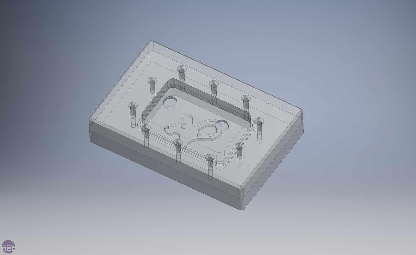
This is our final reservoir! We used the fillet and chamfer tools to round the edges and make everything look pretty. We actually made this to spec - as in, if we exported it as a suitable file type, we could get this CNC cut or 3D printed!
Click to enlarge
I really enjoyed learning these basic steps, and it is something I would like to keep on improving. It isn't as hard as I thought it was going to be. I had tried to teach myself in the past and failed miserably, but having someone there to walk through the steps and show me what each tool did was a great help. Alex does have some further tips to make things a little easier:
- Sketch your drawing on paper first, as this helps you to visualise what you need to create.
- If something isn't working how you want it to, check out other programs. There are multiple tools out there that can help you - use them.
- Watch YouTube videos to learn what each tool does and how best to use it. Inventor also has a lot of instructional material that is worth looking at.
RELATED ARTICLES


MSI MPG Velox 100R Chassis Review
October 14 2021 | 15:04

Want to comment? Please log in.