
Cooler Master has created a one-of-a-kind demo unit to show off some of their new hardware ahead of CeBIT – and it's a pretty impressive powerhouse.
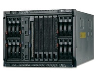
Dubbed the “53GHz”, the system – spotted via Make – is built from five mini-ITX systems housed in one of the company's ATCS 840 cases. Each ITX system houses an Intel Core 2 Quad Q9400 processor alongside 2GB of RAM, for a total of 20 processing cores and 10GB of memory. Each motherboard within the micro-cluster has been given its own hard drive for storage – with the company choosing to use 2.5” small form factor drives to reduce power load and heat output.
While creating a small cluster from micro-sized motherboards is nothing new, what is impressive is that the company is using a single Cooler Master Real Power M1000W PSU to run all five motherboards, using all six +12V rails to ensure system stability.
With so much power housed in a fairly tight case, heat was always going to be a problem. Accordingly, the company has seen fit to add a trio of 200mm fans alongside a single 120mm unit, plus independent water pumps for each ITX unit which feed into a single case-mounted radiator. With this in place, Cooler Master is claiming a 66 degree Celsius temperature for the hottest core at a 30 degree case temperature.
It's a good showcase for the company's current range of power, cooling, and case products – but one with a limited practicality. As each system is independent, the single box requires five keyboards, five mice, and five monitors – along with five people to drive it. That said, any processing task which is suited to a clustered or distributed environment – such as encoding or rendering – would greatly benefit from something such as this demo unit. Sadly, the company has no plans to put the device into production – although there's nothing stopping you buying each item individually and building one yourself.
Impressed with the amount of power the M1000W can output, or is this nothing more than showing off on the company's part? Thinking of the uses to which you could put 20 processing cores? Share your thoughts over in the forums.
RELATED ARTICLES


MSI MPG Velox 100R Chassis Review
October 14 2021 | 15:04

Want to comment? Please log in.