
Making a Fanbus
The fan bus consists of two parts: first the VFD which I have previously covered although I will cover a few more details here where relevant to the fanbus. The second part is the actual electronics and control panel which is housed in a 5 1/4" drive bay. The fanbus has two channels, each with its own fan speed knob and LED bargraph display to indicate relative fan speed.The VFD has eight on/off type outputs which connect to the fan bus PCB. Two of these outputs are used to switch each of the fanbus channels into high speed when an over temperature situation is detected. This also causes the bargraphs to fully light and flash as a warning that things are getting hot! The remaining six outputs are passed through a buffer chip and are available to switch ancillary kit such as case lighting etc.
The VFD also has a keypad input and so I have included four push buttons on the fanbus panel. The function of these buttons is programmable as are the VFD outputs. The VFD control software used is the excellent LCDC which allows great flexibility in configuring the buttons and outputs.
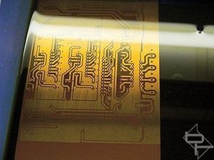
Let's take a look at the fanbus. Like most of my circuits it is built up on a Printed Circuit Board, (PCB). The circuit itself is loosely based on a previous design of mine. The complete circuit is here. It should be noted that this fanbus was made over a weekend during Summer 2001 from parts I had in my scrap box and that some of the components may no longer be available. This circuit is an "incidental" to the entire project and is included purely for completeness and not as a supported project.
After etching and drilling, the PCB was populated with the components.
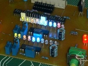
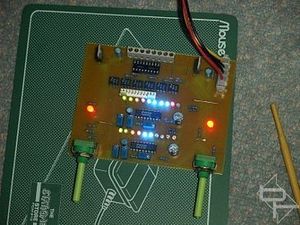
Here, the board is undergoing some initial functional testing. I will cover the various bits on the board as we progress. The two rows of LED's are the fan speed meters and the two large red LED's will illuminate the position marker dot on the control knobs.
In case you hadn't already guessed it, this project makes extensive use of fibre optics to put the lighting exactly where I want it. The pin header behind the second row of LED's is the connection to the VFD for I/O control.
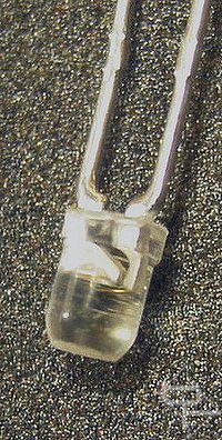
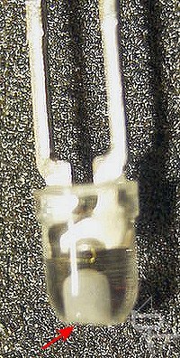
All the 3 mm LED's used in the bargraphs and the 5 mm LED's used to light the control knob position markers were first given a flat top by sanding them down using medium grit wet and dry paper. The flat top makes it easier to drill without the drill bit slipping. A 1mm hole was then drilled into the top to accommodate the fibre optic cable. Care was needed to drill as close to the LED element as possible without actually touching it. Drilling too far would have destroyed the LED whereas too shallow a hole would not have held the fibre optic cable securely.
Lighty-up knobs next...
RELATED ARTICLES


MSI MPG Velox 100R Chassis Review
October 14 2021 | 15:04

Want to comment? Please log in.