Rainbow LED
August 28, 2002 | 00:00

Somewhere, over the rainbow...
Right, let's get straight to the point. This is a little eye-candy circuit which continuously cycles an RGB LED through the colours of the rainbow. The speed at which the colours change is adjustable.
The circuit has two options:
1. Switch between the different colours. This makes the effect very noticeable.
2. Have the colours fade into each other. This is a more relaxed effect and one I find very pleasing. The choice is yours.
The cost is about £2 (ish) plus the LED and PCB
At this point I was planning on having a video of the circuit in action but the exposure on my video camera is only fully automatic. This makes it impossible to get even a half decent clip of a concentrated light source such as an LED. Anyway, the concept is pretty straight forward so your imagination should give you the picture.
Moving swiftly on, here's how the circuit works:
IC1, C1, R4, R5 and VR1 form a standard "555 timer" based pulse generator. The frequency of which, and hence the speed of the effect, is adjusted using the pre-set VR1.
These pulses are fed into IC2, a 4029 binary counter whose outputs continuously count in a binary progression between 1 to 7. These outputs drive the transistors Q1, Q2 and Q3 which, in turn, control each of the three colours of the RGB led.
The pulses are"shaped" by passing them through an RC network before they reach their respective transistors. This "shaping" produces the fading effect between the colours.
The fade in/out time can be altered by changing the value of the capacitors. (C3, C4, C5). Reducing the value to 47uF will reduce the time to fade between colours. Conversely, increasing the capacitance to 200uF will take longer. The value of 100uf for the "fade" capacitor was found by testing to be the most suitable over a wide speed setting range. You may want to experiment with different values, especially at very high and low speed settings. Do not change the R6, R7 and R8 values as this will affect the led current and may damage it.
As stated previously, the circuit can be used without the fading effect and having the colours abruptly change. To do this, just do not fit the fade capacitors, C3, C4 and C5.
A note about the led limiting resistors, R1, R2 and R3. The values shown in the table were derived from calculation and then trimmed to the nearest preferred value by experimentation. The chosen values produce good results without over loading the led. If you use an RGB led with different specs, you may need to use different resistor values, although the circuit should still work using the current values.
The PCB foil pattern below is clickable for a 4x life-size image. Use the 4x image to produce the art work to make the board. The image needs to be reduced to 25% when printing to produce the life-sized foil. Load the foil pattern image into a drawing package such as Paint Shop Pro to print it. Do the reduction at the PRINTING stage and NOT using the resize image tools within the drawing package. Using this reduction method produces sharp artwork.
EAGLE users can download the PCB layout here. The free version of EAGLE can be downloaded here. Or from the Eagle web site download page.
The board size, (the rectangle around the foil), is 34mm x 61mm.
All holes are 0.8mm with the exception of the holes for VR1. These are 1.2mm.
When assembling the PCB start with the smallest components first, working your way up. (Resistors, IC's, transistors, pre-set, capacitors).

RGB LED Specs
RED If = 30mA, Vf = 2.0V
GREEN If = 25mA, Vf = 2.2V
BLUE If = 30mA, VF = 4.5V
LED pin outs viewed from underneath.
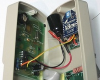
Here's a picture of the completed Rainbow LED. The led can be mounted off board using wires which will make it easier to panel mount.

Any questions? Ask them here.
Happy moddin'.
Right, let's get straight to the point. This is a little eye-candy circuit which continuously cycles an RGB LED through the colours of the rainbow. The speed at which the colours change is adjustable.
The circuit has two options:
1. Switch between the different colours. This makes the effect very noticeable.
2. Have the colours fade into each other. This is a more relaxed effect and one I find very pleasing. The choice is yours.
The cost is about £2 (ish) plus the LED and PCB
At this point I was planning on having a video of the circuit in action but the exposure on my video camera is only fully automatic. This makes it impossible to get even a half decent clip of a concentrated light source such as an LED. Anyway, the concept is pretty straight forward so your imagination should give you the picture.
Moving swiftly on, here's how the circuit works:
IC1, C1, R4, R5 and VR1 form a standard "555 timer" based pulse generator. The frequency of which, and hence the speed of the effect, is adjusted using the pre-set VR1.
These pulses are fed into IC2, a 4029 binary counter whose outputs continuously count in a binary progression between 1 to 7. These outputs drive the transistors Q1, Q2 and Q3 which, in turn, control each of the three colours of the RGB led.
The pulses are"shaped" by passing them through an RC network before they reach their respective transistors. This "shaping" produces the fading effect between the colours.
The fade in/out time can be altered by changing the value of the capacitors. (C3, C4, C5). Reducing the value to 47uF will reduce the time to fade between colours. Conversely, increasing the capacitance to 200uF will take longer. The value of 100uf for the "fade" capacitor was found by testing to be the most suitable over a wide speed setting range. You may want to experiment with different values, especially at very high and low speed settings. Do not change the R6, R7 and R8 values as this will affect the led current and may damage it.
As stated previously, the circuit can be used without the fading effect and having the colours abruptly change. To do this, just do not fit the fade capacitors, C3, C4 and C5.
A note about the led limiting resistors, R1, R2 and R3. The values shown in the table were derived from calculation and then trimmed to the nearest preferred value by experimentation. The chosen values produce good results without over loading the led. If you use an RGB led with different specs, you may need to use different resistor values, although the circuit should still work using the current values.
The PCB foil pattern below is clickable for a 4x life-size image. Use the 4x image to produce the art work to make the board. The image needs to be reduced to 25% when printing to produce the life-sized foil. Load the foil pattern image into a drawing package such as Paint Shop Pro to print it. Do the reduction at the PRINTING stage and NOT using the resize image tools within the drawing package. Using this reduction method produces sharp artwork.
EAGLE users can download the PCB layout here. The free version of EAGLE can be downloaded here. Or from the Eagle web site download page.
The board size, (the rectangle around the foil), is 34mm x 61mm.
All holes are 0.8mm with the exception of the holes for VR1. These are 1.2mm.
When assembling the PCB start with the smallest components first, working your way up. (Resistors, IC's, transistors, pre-set, capacitors).
RGB LED Specs
RED If = 30mA, Vf = 2.0V
GREEN If = 25mA, Vf = 2.2V
BLUE If = 30mA, VF = 4.5V
LED pin outs viewed from underneath.
Here's a picture of the completed Rainbow LED. The led can be mounted off board using wires which will make it easier to panel mount.
Any questions? Ask them here.
Happy moddin'.


MSI MPG Velox 100R Chassis Review
October 14 2021 | 15:04

Want to comment? Please log in.