
Simple Fan Speed Control
Here is a simple mod to allow the speed of any 12V fan to be varied.
All we need to do is insert a rheostat or variable resistor in the 12V wire to the fan. The rheostat should be rated at least 3 Watt, (for fans up to 10Watt), and have a resistance of 20 – 50 Ohms. If you are using this mod on your CPU fan then use the 20 ohm rheostat to prevent fan stall at the slowest speed setting.
Maplin Stock codes
20 ohm = FX40T
50 ohm = FX97F
In the procedure below I have used a 4way Molex extender cable, (the type used to extend PSU leads), but you can just as easily connect the rheostat directly to the fan wires if you prefer. If you choose to apply this mod directly to the fan wires, make sure you connect the rheostat to the 12V wire. (Red) You can double check by plugging the fan into the PSU and note which wire connects to the Yellow wire from the PSU. This will be the 12V wire. (Of course, do this with it turned off!).
BE VERY CAREFUL when fixing the rheostat to the case that there is no possibility of it shorting to the metalwork. If it does you will be directly shorting out the 12V supply…..Be safe, double check your work before switching on.
Right, let’s get on with it………
Step 1.
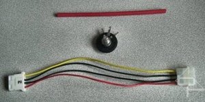
The rheostat, extender lead and some heat-shrink sleeving for insulation.
Step 2.
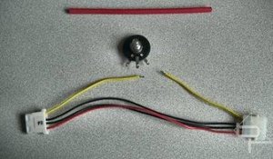
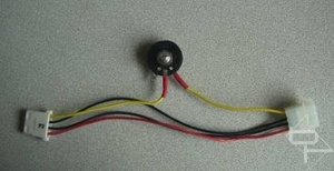
Cut and strip the ends of the 12V wire, (Yellow in this case, Red if fitting rheostat directly to the fan wire). NOT the red wire in the picture, the one on the fan.
Step 3.
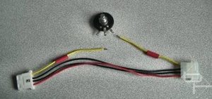
Slide some heat-shrink sleeving over the wire ends.
Step 4.
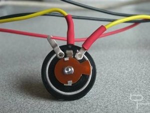
Solder the wires to the rheostat. Note which 2 out of the 3 rheostat terminals are used. This way, turning the rheostat clockwise will increase fan speed. Don’t get the heat-shrink Sleeving too close when soldering or it will shrink and not fit over the terminals when you are done.
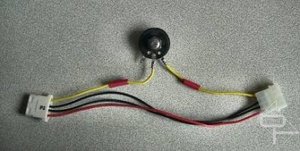
Step5.
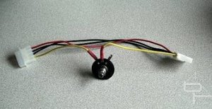
Slide the heat-shrink over the soldered terminals and heat with a hairdryer to shrink it !
Gratuitous behind shot of the soldered rheostat
Nearly finished.
Step 6.
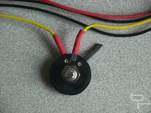
Fit some heat-shrink over the unused rheostat terminal to help prevent any short circuits when fitted in the case.
Step 7.
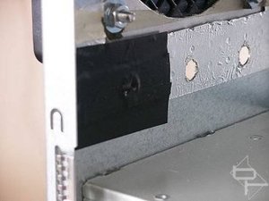
Decide on a suitable location for the rheostat and drill a hole in the case for it. Surround the area with a layer of insulation tape for added protection against short circuits.
Step 8.
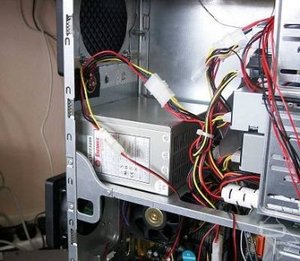
Fit the rheostat and plug it in. Here it is controlling an 80mm Delta “Screamer” on the CPU cooler.
Step 9.
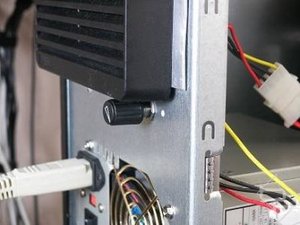
This is what it looks like from outside the case.
Happy Moddin\'.
Here is a simple mod to allow the speed of any 12V fan to be varied.
All we need to do is insert a rheostat or variable resistor in the 12V wire to the fan. The rheostat should be rated at least 3 Watt, (for fans up to 10Watt), and have a resistance of 20 – 50 Ohms. If you are using this mod on your CPU fan then use the 20 ohm rheostat to prevent fan stall at the slowest speed setting.
Maplin Stock codes
20 ohm = FX40T
50 ohm = FX97F
In the procedure below I have used a 4way Molex extender cable, (the type used to extend PSU leads), but you can just as easily connect the rheostat directly to the fan wires if you prefer. If you choose to apply this mod directly to the fan wires, make sure you connect the rheostat to the 12V wire. (Red) You can double check by plugging the fan into the PSU and note which wire connects to the Yellow wire from the PSU. This will be the 12V wire. (Of course, do this with it turned off!).
BE VERY CAREFUL when fixing the rheostat to the case that there is no possibility of it shorting to the metalwork. If it does you will be directly shorting out the 12V supply…..Be safe, double check your work before switching on.
Right, let’s get on with it………
Step 1.
The rheostat, extender lead and some heat-shrink sleeving for insulation.
Step 2.
Cut and strip the ends of the 12V wire, (Yellow in this case, Red if fitting rheostat directly to the fan wire). NOT the red wire in the picture, the one on the fan.
Step 3.
Slide some heat-shrink sleeving over the wire ends.
Step 4.
Solder the wires to the rheostat. Note which 2 out of the 3 rheostat terminals are used. This way, turning the rheostat clockwise will increase fan speed. Don’t get the heat-shrink Sleeving too close when soldering or it will shrink and not fit over the terminals when you are done.
Step5.
Slide the heat-shrink over the soldered terminals and heat with a hairdryer to shrink it !
Gratuitous behind shot of the soldered rheostat
Nearly finished.
Step 6.
Fit some heat-shrink over the unused rheostat terminal to help prevent any short circuits when fitted in the case.
Step 7.
Decide on a suitable location for the rheostat and drill a hole in the case for it. Surround the area with a layer of insulation tape for added protection against short circuits.
Step 8.
Fit the rheostat and plug it in. Here it is controlling an 80mm Delta “Screamer” on the CPU cooler.
Step 9.
This is what it looks like from outside the case.
Happy Moddin\'.
RELATED ARTICLES


MSI MPG Velox 100R Chassis Review
October 14 2021 | 15:04

Want to comment? Please log in.