
PWM or Pulse Width Modulation has generally been regarded as too complicated for PC fan speed control compared against using rheostats or linear voltage regulators such as the LM317. I present here a PWM circuit that is simple and cheap enough to be built by the casual electronics builder.
Why would you want to use PWM instead of a rheostat or voltage regulator? Well, like most things, each method has it's own strengths and disadvantages:
Pros: Cheap and easy to use.
Cons: Difficult to find suitable rheostats, introduces current limiting causing the fan to fail to start or stall at slow speed settings.
Pros: Does not have rheostat like current limiting, temperature control can be incorporated.
Cons: Regulator can generate considerable heat which limits the maximum fan power. (The more powerful the fan, the more heat is generated), maximum output voltage to the fan can be several volts less than the supply limiting the maximum cooling from the fan. (A by-pass switch can be fitted to eliminate this problem, but this adds to the complexity of the circuit).
Pros: As linear voltage regulator, plus comparatively little heat is generated by the circuit allowing higher powered fans to be used, output is virtually 0-100%, eliminating the need for a bypass switch, fans do not stall or fail to start at minimum fan speed.
Cons: The fan speed sensing is disabled, can cause "growling" noises at very low speed settings with some fans.
What is PWM? In simple terms, PWM involves rapidly switching the supply to the fan on and off, in this case 30 times a second, (30Hz). By altering the relative on to off times the average voltage "seen" by the fan is also altered. E.G. Assuming a 12V supply, when the on/off ratio = 50%/50% the fan will "see" 6V, likewise when the on/off ratio is 75%/25% the fan "sees" 9V. Obviously 100% output is achieved by having the output on continuously and at 0% the output is off. It is this on/off switching that makes the fan speed sensor inoperative.
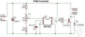
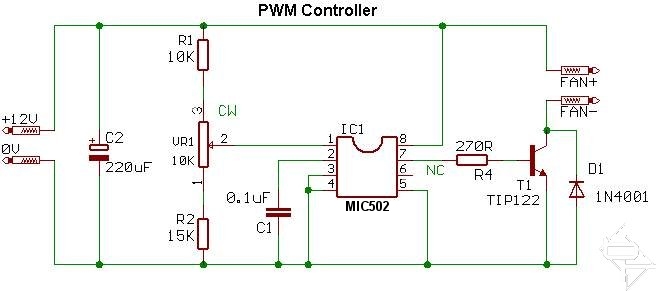
The circuit uses a purpose made chip, MIC502 made by MICREL. Fan speed is adjusted by varying VR1. With the component values shown the output is 40%-100%. ( 4.8 - 12V). So far every fan I have tested runs at 4.8V. To guarantee the fan starts when the computer is switched on, the chip automatically runs the fan at full output for approximately 2 seconds before dropping to the preset speed. Changing the value of R1 and R2 to 7K5 ohms will give an output range of 0% - 100%.
If desired, R1 and R2 can be replaced with 22K variable preset resistors to allow exact tailoring of the control range. Varying R1 will alter the maximum output, whilst R2 controls the minimum. Note these adjustments are interactive with each other and will require some trial and error to achieve the desired range. The diode, D1 is to protect the transistor from reverse voltage spikes when switching the fan off. Using modern DC axial fans should not be a problem and D1 may be considered optional. Since I cannot test every possible device people may connect to the circuit I have included D1 for completeness.
On the other hand, the decoupling capacitor, C2 is NOT optional. During testing it became apparent that the chip does not like "noisy" supplies. E.G. My 350W " Enermax has very long leads and poor quality connectors. This does not help maintain a clean supply. Things may be different for you but I consider C2 to be necessary. C1 sets the pulse frequency, in this case 30Hz.
During testing "growl" noise at low speeds was not a problem. If "growl" is a problem with your specific fan then changing the value of C1 should help. Use the formula C = 3/f where C is in microfarad (uF) and f is the desired frequency in hertz (Hz). Try frequencies in the range 30-100 Hz. R4 limits the base current to the transistor T1. T1 is rated at 5A which equates to 60W of fan!! In practise the circuit should be capable of running any reasonable number of case fans. With several powerful fans connected the transistor may get warm so a small heatsink may be required.
Several channels can be made to make a multi channel fan bus. Only one "C2" is required if all the channels are built on the same board. Looking at the circuit diagram, the "+12V" and "0V" terminals connect to the respective connections on the PSU Molex connector. The "FAN+" and "FAN-" connect to the corresponding +v and -v terminals on the fan.
Adding Temperature control.
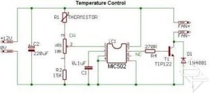
Here the resistor R1 has been replaced with a thermistor to give temperature control. The fan speed is set by VR1 and as the temperature rises, so the fan speed will increase to compensate.
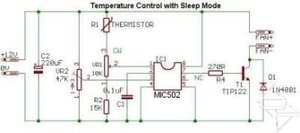
This version is identical to the temperature control above, except for the addition of a "sleep" setting. The idea is to turn the fan off when the temperature falls below the value set by VR2.
Why would you want to use PWM instead of a rheostat or voltage regulator? Well, like most things, each method has it's own strengths and disadvantages:
Rheostats
Pros: Cheap and easy to use.
Cons: Difficult to find suitable rheostats, introduces current limiting causing the fan to fail to start or stall at slow speed settings.
Linear voltage regulators
Pros: Does not have rheostat like current limiting, temperature control can be incorporated.
Cons: Regulator can generate considerable heat which limits the maximum fan power. (The more powerful the fan, the more heat is generated), maximum output voltage to the fan can be several volts less than the supply limiting the maximum cooling from the fan. (A by-pass switch can be fitted to eliminate this problem, but this adds to the complexity of the circuit).
PWM
Pros: As linear voltage regulator, plus comparatively little heat is generated by the circuit allowing higher powered fans to be used, output is virtually 0-100%, eliminating the need for a bypass switch, fans do not stall or fail to start at minimum fan speed.
Cons: The fan speed sensing is disabled, can cause "growling" noises at very low speed settings with some fans.
What is PWM? In simple terms, PWM involves rapidly switching the supply to the fan on and off, in this case 30 times a second, (30Hz). By altering the relative on to off times the average voltage "seen" by the fan is also altered. E.G. Assuming a 12V supply, when the on/off ratio = 50%/50% the fan will "see" 6V, likewise when the on/off ratio is 75%/25% the fan "sees" 9V. Obviously 100% output is achieved by having the output on continuously and at 0% the output is off. It is this on/off switching that makes the fan speed sensor inoperative.
The circuit uses a purpose made chip, MIC502 made by MICREL. Fan speed is adjusted by varying VR1. With the component values shown the output is 40%-100%. ( 4.8 - 12V). So far every fan I have tested runs at 4.8V. To guarantee the fan starts when the computer is switched on, the chip automatically runs the fan at full output for approximately 2 seconds before dropping to the preset speed. Changing the value of R1 and R2 to 7K5 ohms will give an output range of 0% - 100%.
If desired, R1 and R2 can be replaced with 22K variable preset resistors to allow exact tailoring of the control range. Varying R1 will alter the maximum output, whilst R2 controls the minimum. Note these adjustments are interactive with each other and will require some trial and error to achieve the desired range. The diode, D1 is to protect the transistor from reverse voltage spikes when switching the fan off. Using modern DC axial fans should not be a problem and D1 may be considered optional. Since I cannot test every possible device people may connect to the circuit I have included D1 for completeness.
On the other hand, the decoupling capacitor, C2 is NOT optional. During testing it became apparent that the chip does not like "noisy" supplies. E.G. My 350W " Enermax has very long leads and poor quality connectors. This does not help maintain a clean supply. Things may be different for you but I consider C2 to be necessary. C1 sets the pulse frequency, in this case 30Hz.
During testing "growl" noise at low speeds was not a problem. If "growl" is a problem with your specific fan then changing the value of C1 should help. Use the formula C = 3/f where C is in microfarad (uF) and f is the desired frequency in hertz (Hz). Try frequencies in the range 30-100 Hz. R4 limits the base current to the transistor T1. T1 is rated at 5A which equates to 60W of fan!! In practise the circuit should be capable of running any reasonable number of case fans. With several powerful fans connected the transistor may get warm so a small heatsink may be required.
Several channels can be made to make a multi channel fan bus. Only one "C2" is required if all the channels are built on the same board. Looking at the circuit diagram, the "+12V" and "0V" terminals connect to the respective connections on the PSU Molex connector. The "FAN+" and "FAN-" connect to the corresponding +v and -v terminals on the fan.
Adding Temperature control.
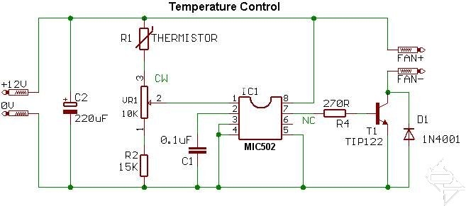
Here the resistor R1 has been replaced with a thermistor to give temperature control. The fan speed is set by VR1 and as the temperature rises, so the fan speed will increase to compensate.
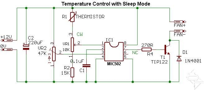
This version is identical to the temperature control above, except for the addition of a "sleep" setting. The idea is to turn the fan off when the temperature falls below the value set by VR2.


MSI MPG Velox 100R Chassis Review
October 14 2021 | 15:04

Want to comment? Please log in.