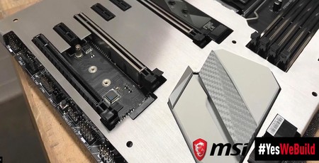
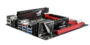
Now, you may remember this MSI Z370 Gaming Pro Carbon AC that we gave a lick of paint in a previous video and article. Well, with the newfound capabilities of my workshop, it seemed fitting that we revisit that board and see what else can be done to it!
Motherboard "armour"/shrouds have been a note of contention since modders first started incorporating the feature into their builds. Whilst the sometimes fantastically clean aesthetic meant you could have a lot of flexibility in matching other parts of a rig, often it resulted in a loss of thermal performance, with some boards not enjoying being enclosed and others needing whiny, tiny fans to lend a hand. Nowadays though, so much is built into the CPU itself that good chunks of a motherboard PCB can be safely covered up without much issue. You only need to have a glance across current high-end options to see how popular the look is.
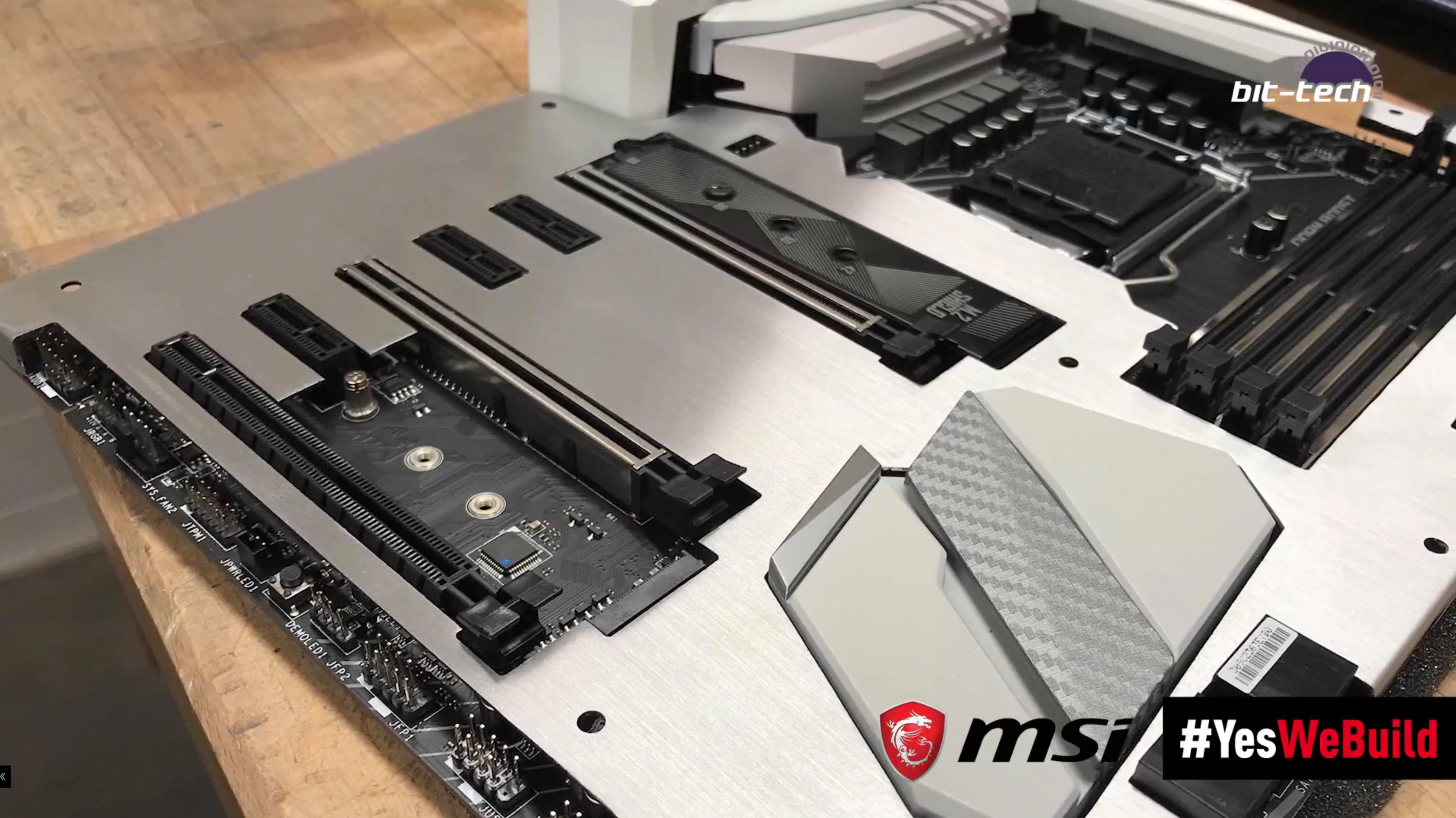
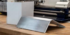
So, to keep up with the Joneses, we're going to make an aluminium shroud for this board. In order to fit with the theme of the graphics card and cooler, why not stick to a classy brushed effect whilst we're at it?
It's worth noting before we get going, I'm using a CNC router because that's what I have access to. This mod could quite easily be done by hand; you will just have to be careful when drawing your template to make sure you can cut he necessary shapes. See our article on Making Cutting Templates for more info on that!
We Need a Plan
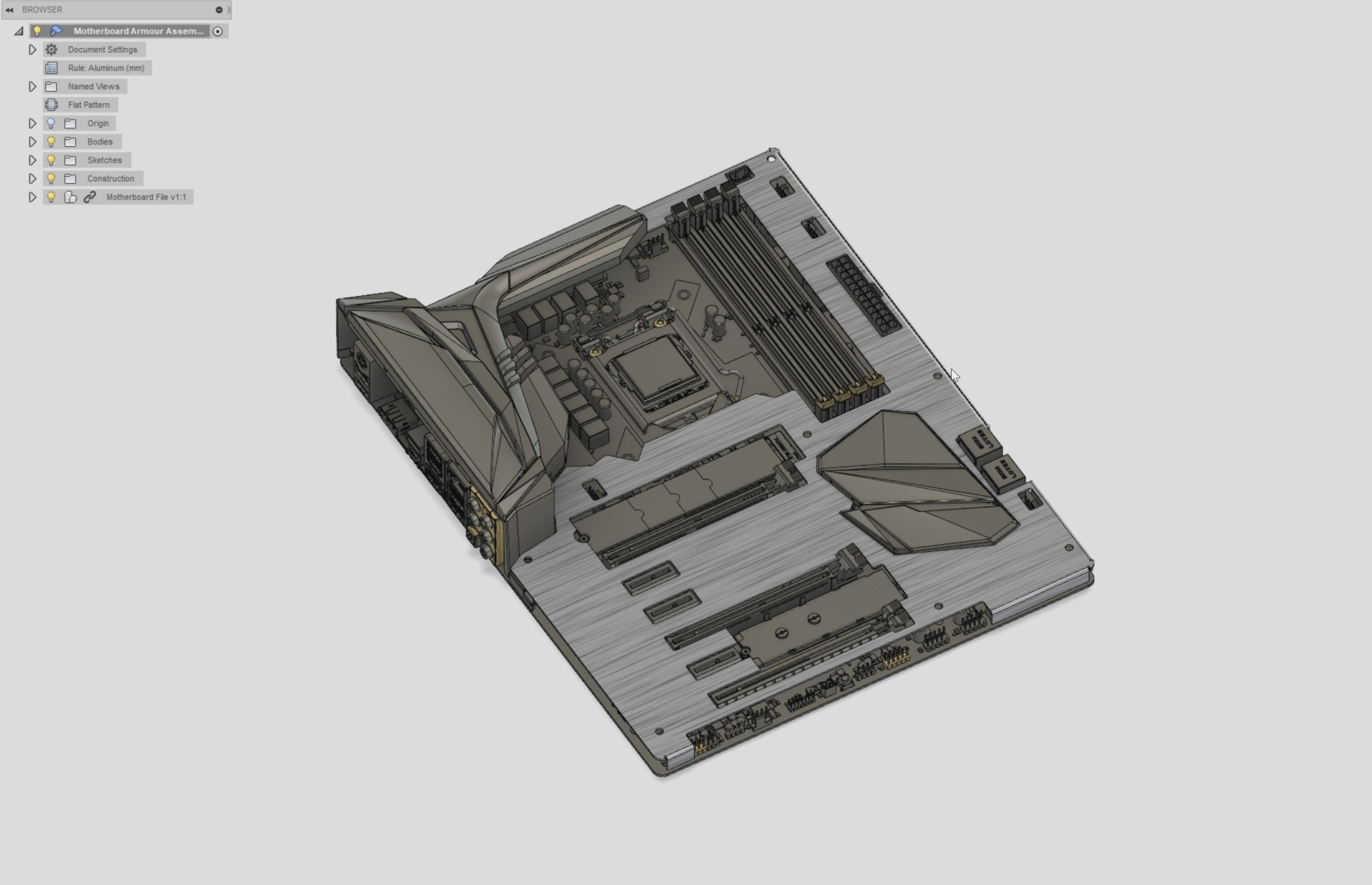
The way I would approach a part like this is through CAD software, my personal choice currently being Autodesk's Fusion 360. I'm working from an approved and accurate step file for this mod, again because that's what I have access to. If you don't have access to that sort of reference material, don't fret. First up, there may well be a high quality model of your board floating around online, so check sites like GrabCAD to see if somebody's already done the leg work.
Failing that, simply pull out some calipers and get measuring! It sounds daunting, but much of the most crucial information is actually available via the ATX Specification where you'll find info like accurate board measurements and placement for things like the PCIe slots and so on. That info will help reduce error and give you less manual work to do.
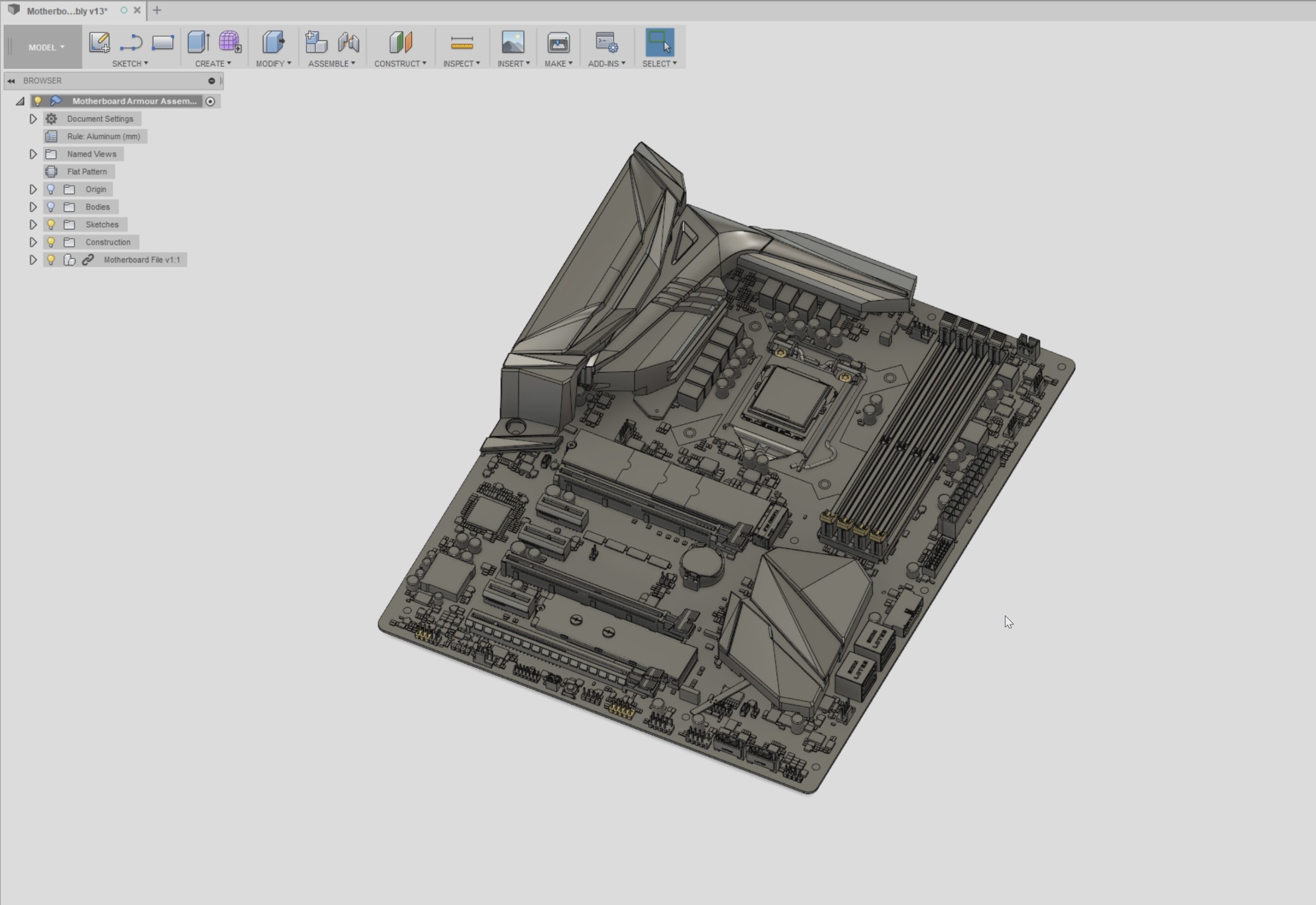
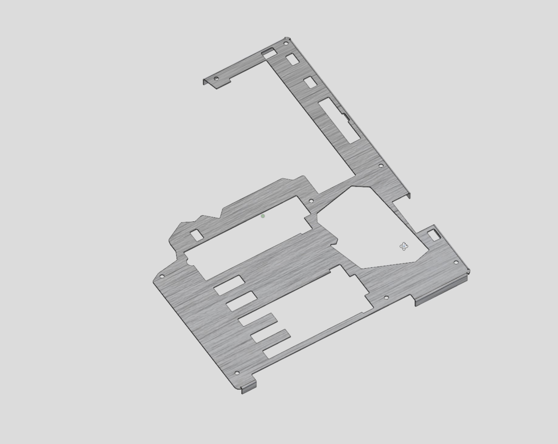
To design the actual shroud itself, I'm going to be using the sheet metal environment within Fusion 360. Since we're going to be using 1mm aluminium sheet to make the real part, it just makes sense to use the correct modelling environment, as that way you can use handy features like the fold/unfold commands to produce a template. Creating a new component, I sketched over the geometry of the motherboard, leaving a 0.5mm clearance between the edge of the metal and any of the parts. The shroud will be held 10mm above the surface of the PCB, which will be enough for it to clear any capacitors etc.
The more detailed your starting model, the quicker this process is. Since I can measure the component heights and see where they lie on the board, making room for fan headers, RGB connectors, and power cables is straightforward. If doing this from scratch, make sure to be thorough, else you'll find yourself constantly going back and forth to fix oversights later on.
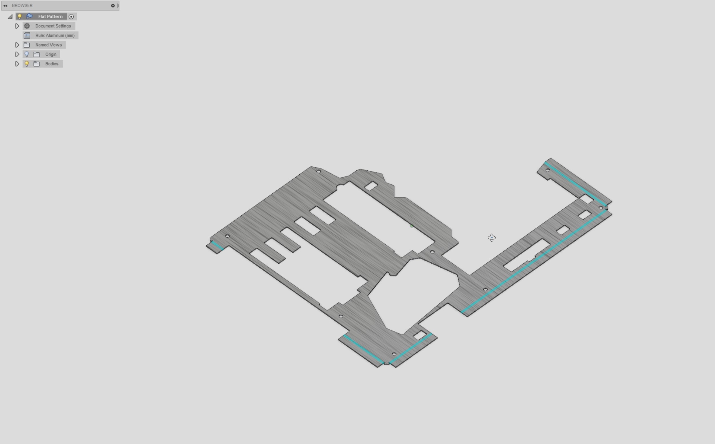
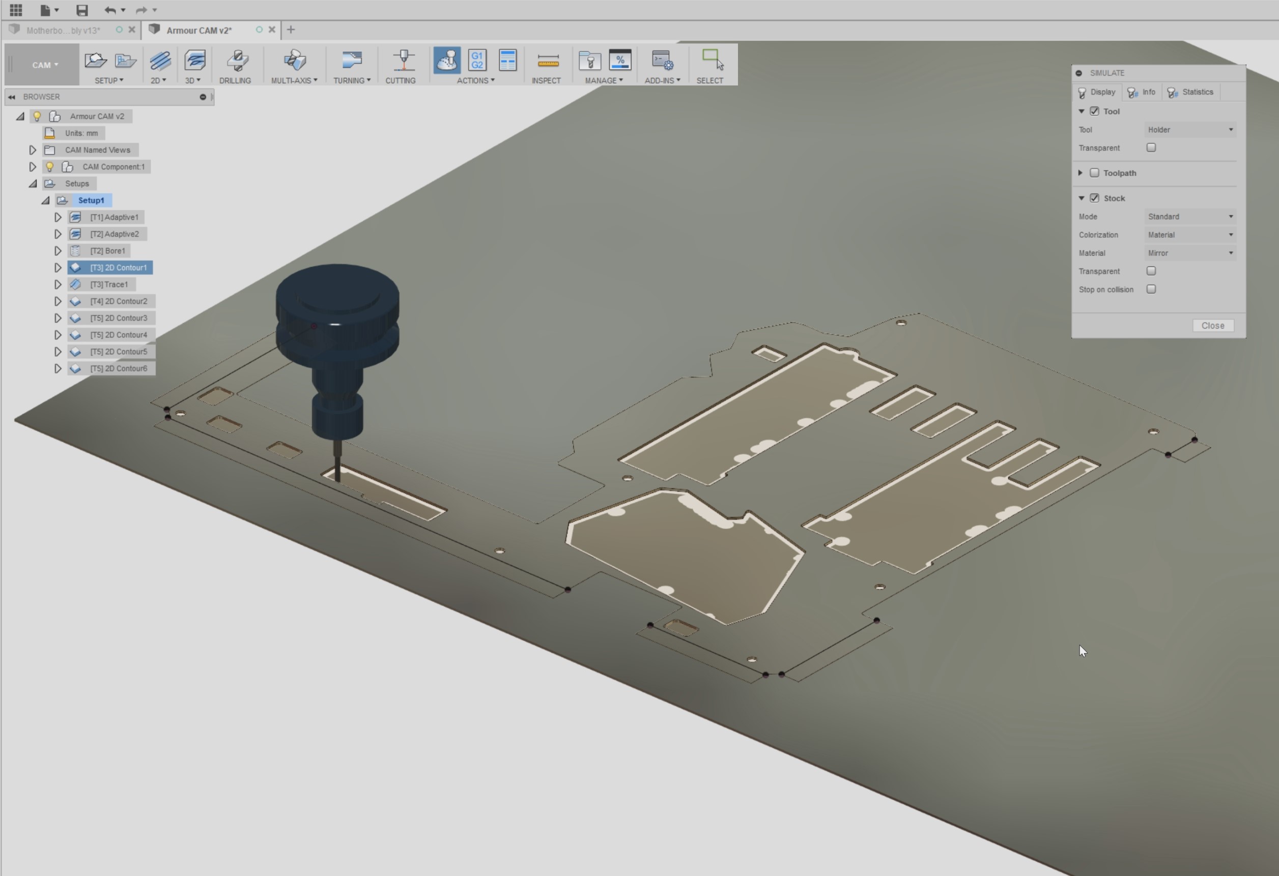
With the part modelled, the real advantage of using sheet metal rears its head. The flanges on the outside were modelled with a pre-defined bend radius, and within the program you're able to flatten the whole model, providing either a template for printing off or for processing in CAM for use with a machine. Once flattened, I moved to the CAM environment within Fusion in order to begin setting up the toolpathing.
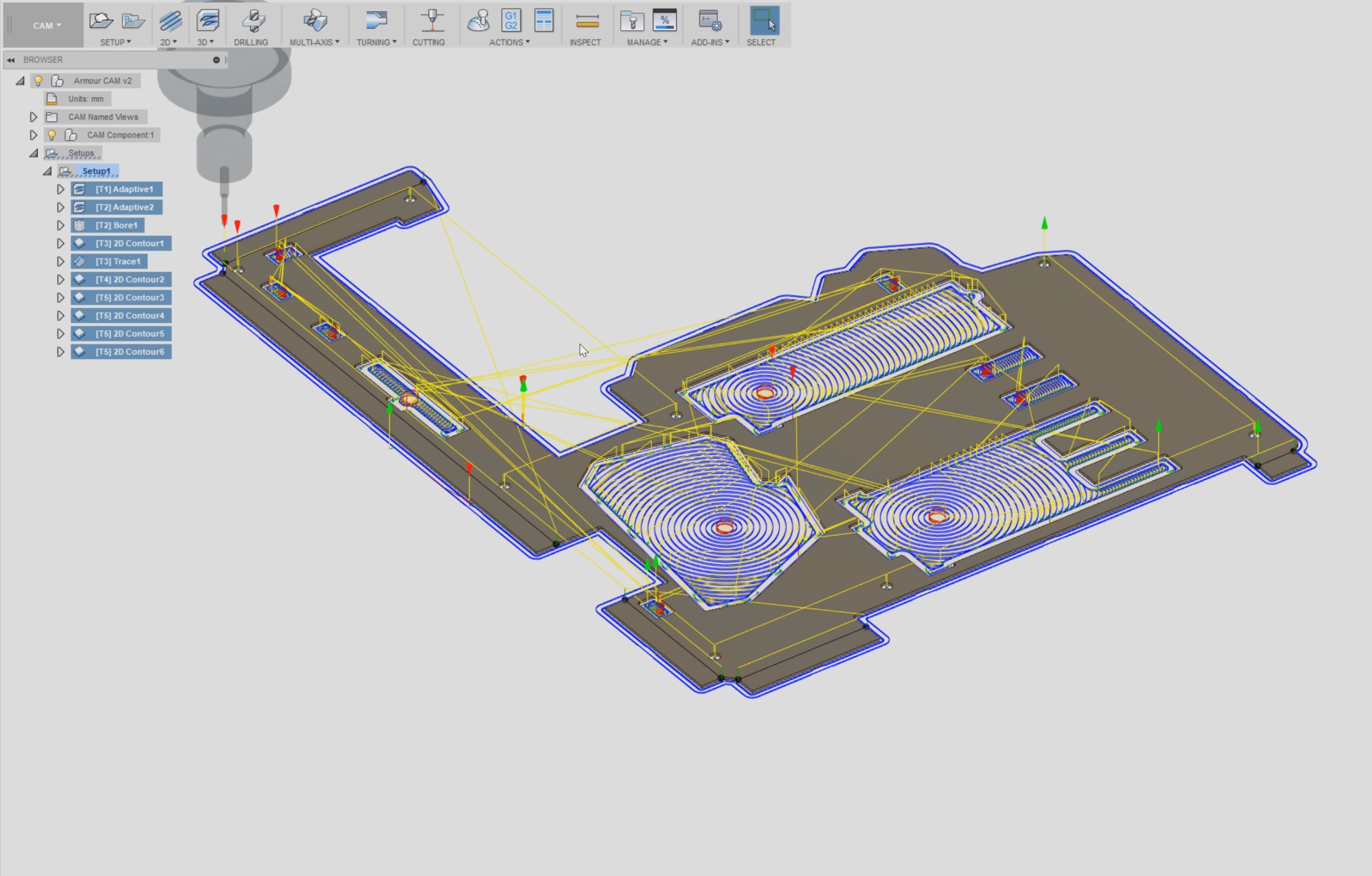
Now, I'll be the first to admit I didn't need to pocket mill this part - at all. I just wasn't 100 percent sure about the grade of the material, so I wanted to avoid slotting so that it wouldn't clog the endmill (2mm for the corners). We had one shot to get this done on time, so it was worth it, but I've since cut plenty of other pieces with more optimised toolpaths, I promise!
To help keep the bends crisp, I figured it would be a good idea to score the inside surface using a 2mm endmill to a depth of 0.5mm. 1mm aluminium is very easy to bend, but some of the header locations are near the flanges, so I didn't want them to distort by accident. Last step is to hit preview, then it's onto the machine!
RELATED ARTICLES


MSI MPG Velox 100R Chassis Review
October 14 2021 | 15:04

Want to comment? Please log in.