

The fins of the fans are small compared to the motors in the centre, so they have to spin fast in order to create a decent airflow. One centrally placed fan could do the job just as well as two and leave more space on the rear I/O. The whole heatsink/fan combo could even be redesigned similar to a 1U server heatsink that sits on top at an angle to push the air down and out. This would allow for a quieter and larger 60x10mm, whilst still not going over ATX spec. Luckily the fans can be unplugged without too much fuss, as they use a standard 3-pin connector.
All the plug sockets are placed sufficiently well in order for easy access without conflict. The SATA, IDE and power ports are all around the edges of the board except for the additional Molex power, which is placed just above the upper PCI-Express x16 slot. This means dragging a cable to the other side of the board, but it sits above the graphics card and is routable around the CPU heatsink. Interestingly, the 12V additional power socket is a simple 4-pin rather than the newer 8-pin variety. Considering that an 8-pin is backward compatible to 4-pin and 8-pin distributes the extra power requirement better, this board is missing out.
USB 2.0 and Firewire pin-outs are adorned in blue and red respectively, and are placed in regular, easy to access places. The front panel pin-outs are also colour coded to allow ease of identification. Also on the board is a LED hex readout in order to identify POST problems, should they occur.
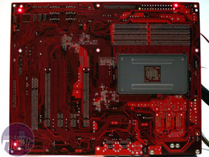
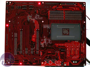
Abit also include some flashing red LEDs on the rear of the board. Whilst these offer a novelty underglow to the motherboard, and whilst not a bad inclusion they do get annoying after a while and cannot be turned to a consistent state (all on or off) in the BIOS.
Unfortunately Abit has gone for the "single PCI slot underneath the second PCI-Express x16 slot" again, which is confusing since Mr. Wendel has “influence on the design” of the board. Since he also endorses the Creative X-Fi Fatal1ty series, you'd think that he would make sure you can run high end SLI graphics cards which usually involve dual slot coolers, along with a PCI Fatal1ty X-Fi sound card.
Saying that, there is a two-slot gap under the first PCI-Express x16 slot to allow plenty of airflow. However, the clips for the card release are on the wrong (under)side, which means it's fiddly to get around the graphics card heatsink to flip the catch whilst pulling the card out.
The space for a bottom PCI slot is lost to the included AudioMAX daughter board as well as a few other components. The AudioMAX board has the Realtek ALC882D codec which has Dolby Digital support as well as standard 7.1 Channel High-definition surround-sound audio, through either the six 3.5mm jacks or the optical S/PDIF out. There's also S/PDIF in, as the upper, blue 3.5mm jack doubles up with use of an adapter; although we’re still missing coaxial S/PDIF for the complete complement.
Half of the capacitors are solid state, which are mostly around the CPU area, and half are standard Japanese Rubycon dotted around the rest of the board. The standard capacitors are of high quality, but they still don't last as long as the solid state variety. Considering that a couple of graphics cards can pull a total of equal 150W from both PCI-Express x16 slots, they should really have been solid state for these expansion ports as well.
Dual PHY (Physical Layer) Gigabit Ethernet is provided by Marvell, connected directly to the MCP southbridge rather than having to negotiate a PCI-Express bus - this lowers the overhead required for networking. This also allows NVIDIA to do clever things like teaming of ports to either provide redundancy or a two Gigabit Ethernet link suitable for a games server, as well as TCP/IP offload to not choke up essential CPU cycles that could mean the difference between frag or failure.


MSI MPG Velox 100R Chassis Review
October 14 2021 | 15:04

Want to comment? Please log in.