
Front Switches
I also got busy and wired up my front switches. It did require a bit of thought as I had to somehow disguise/hide the bare wire connections and make everything fit with the themes.
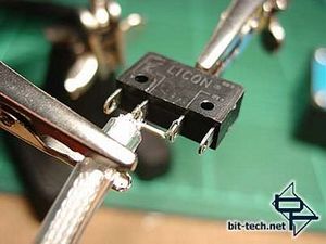
Four of the switches required both sets of contacts wired up - \'normally off\' to a cable for the LED controllers and \'normally on\', via the junction box, back to indicator LEDs over each switch. When the switch is pressed two things will happen: The LED will wink out to let you know you have pressed the switch and the LED controller will cycle to the next of 10 lighting/scanning patterns. The remaining two switches are power and reset and only require the one cable running to the motherboard. Notice I have wired these to jack plugs rather than the normal pin header plugs? I have a plan for a mini switchbay for the motherboard headers but more on that in a later article.
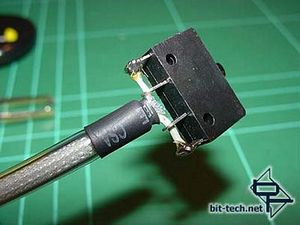
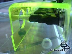
I wired them up as shown (note this is the reset switch so only the one cable) and then proceeded to add layers of heatshrink. I used a black marker pen to cover the white text on the heatshrink and applied it so it would face down and be invisible (the marker will stop you seeing any writing reflected in the acrylic at the bottom of the case). I also carefully measured and cut the respective layers to the same length to ensure an identical appearance once applied. A base layer was added to hold things securely in place ...
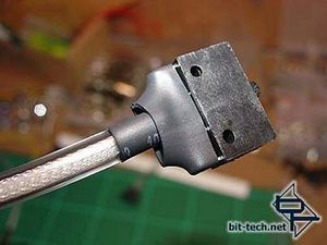
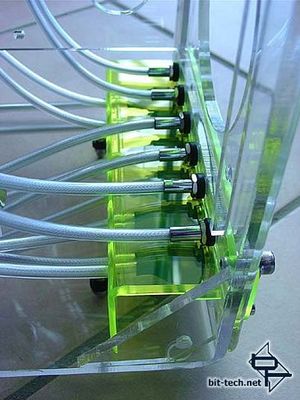
... and a top layer added to hide it all. The top layer extends out from the back of the plug and neatens the cables as well as providing a lot of strength to the whole assembly. With the 4 switches that will have 2 cables coming off them, I wired the first cable offset from the centre so that the second could be wired up next to it and thus have the 2 cables centred nicely coming off the back of the switch. Looks much better.

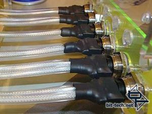
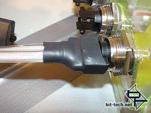
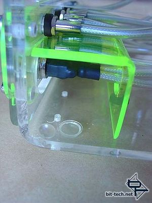
These were clipped onto the front switches. The heatshrink fits perfectly around the clips.
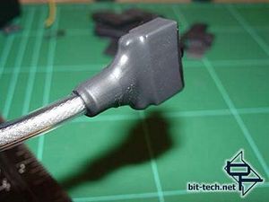
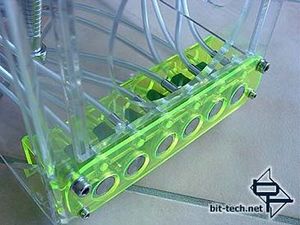
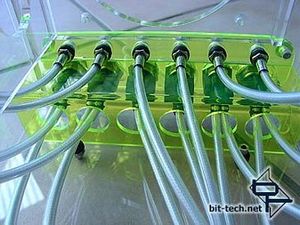
The Power/Reset switches had one more layer added to close off a gap due to the heatshrink from the switch being a little large for a single cable. To balance things I decided to locate my power/reset switches side-by-side in the centre of the switch panel and the LED switches either side. I plan on creating a range of small graphics later to label the front switches (minimalist, modern and set behind the green plexi). The LEDs were then wired up and inserted in their chrome holders - two Green (Pow/Reset) and four White (for the LED controllers).
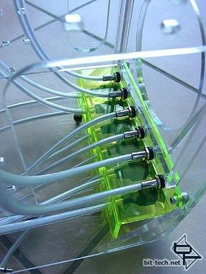
The whole effect fitted in with my theme and I was really happy with how the back of the switches looks. Maybe not to everyones taste, but it has that BBC Special Effects Workshop look to it and the backs will be mostly hidden from view by later components.
Not having had Vandal switches on anything before I sat there pressing away just listening to the tiny click over and over grinning stupidly until I was physically dragged away Nooooooo......give me one more minute....pleeeeze...! I have to admit, they are a nice switch (once again, I think I need to get out more)...
I also got busy and wired up my front switches. It did require a bit of thought as I had to somehow disguise/hide the bare wire connections and make everything fit with the themes.
Four of the switches required both sets of contacts wired up - \'normally off\' to a cable for the LED controllers and \'normally on\', via the junction box, back to indicator LEDs over each switch. When the switch is pressed two things will happen: The LED will wink out to let you know you have pressed the switch and the LED controller will cycle to the next of 10 lighting/scanning patterns. The remaining two switches are power and reset and only require the one cable running to the motherboard. Notice I have wired these to jack plugs rather than the normal pin header plugs? I have a plan for a mini switchbay for the motherboard headers but more on that in a later article.
I wired them up as shown (note this is the reset switch so only the one cable) and then proceeded to add layers of heatshrink. I used a black marker pen to cover the white text on the heatshrink and applied it so it would face down and be invisible (the marker will stop you seeing any writing reflected in the acrylic at the bottom of the case). I also carefully measured and cut the respective layers to the same length to ensure an identical appearance once applied. A base layer was added to hold things securely in place ...
... and a top layer added to hide it all. The top layer extends out from the back of the plug and neatens the cables as well as providing a lot of strength to the whole assembly. With the 4 switches that will have 2 cables coming off them, I wired the first cable offset from the centre so that the second could be wired up next to it and thus have the 2 cables centred nicely coming off the back of the switch. Looks much better.
These were clipped onto the front switches. The heatshrink fits perfectly around the clips.
The Power/Reset switches had one more layer added to close off a gap due to the heatshrink from the switch being a little large for a single cable. To balance things I decided to locate my power/reset switches side-by-side in the centre of the switch panel and the LED switches either side. I plan on creating a range of small graphics later to label the front switches (minimalist, modern and set behind the green plexi). The LEDs were then wired up and inserted in their chrome holders - two Green (Pow/Reset) and four White (for the LED controllers).
The whole effect fitted in with my theme and I was really happy with how the back of the switches looks. Maybe not to everyones taste, but it has that BBC Special Effects Workshop look to it and the backs will be mostly hidden from view by later components.
Not having had Vandal switches on anything before I sat there pressing away just listening to the tiny click over and over grinning stupidly until I was physically dragged away Nooooooo......give me one more minute....pleeeeze...! I have to admit, they are a nice switch (once again, I think I need to get out more)...


MSI MPG Velox 100R Chassis Review
October 14 2021 | 15:04

Want to comment? Please log in.