CAM
Honestly, for this one I really do recommend you watch through the video, as it’s much clearer being able to see everything as it happens.
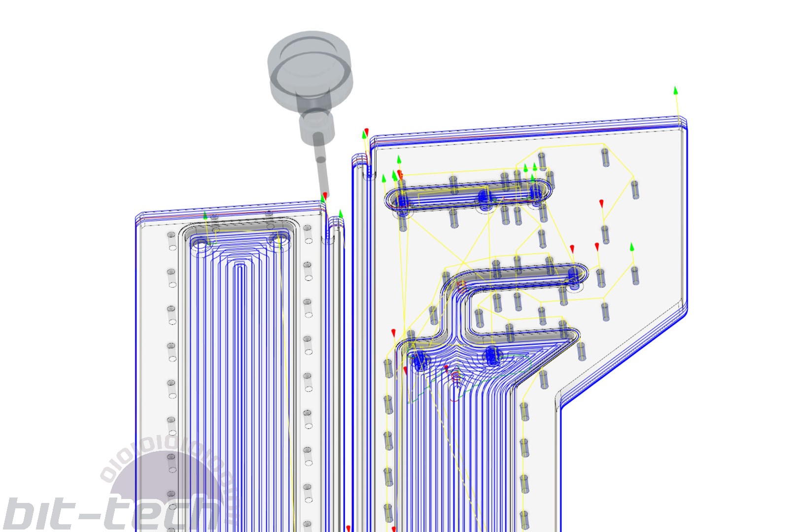
Your toolpathing will dictate the entire cutting process, so it’s incredibly important. It’s a topic of huge scope, as there is no single best approach; realistically it’s more akin to picking your way through a squishy marshland. Which techniques and methods you use will be heavily based around your design, your available tooling, and your workholding.
Here are some pointers that should help. In the video I go over the specific toolpath choices I make for that distro plate, these are more general:
- Drill your holes first – This isn’t essential, more like a quality of life tip. I’ve found that of all the operations I use regularly, drilling holes and thread milling have higher chances of failure compared to regular cutting. It makes sense: You’re cutting deeply into the material without much room for chip evacuation. In the case of thread milling, I’ve found that if my tool has worn down, it will simply melt the plastic, which is no bueno. By doing this part first you can often spot an error early on and easily correct it, potentially saving the material (it’s much easier to avoid a single hole than a whole pocket) or time. Additionally, if like me you use carbide drills for the holes, there aren’t strong lateral cutting forces, meaning the holes should be perfectly aligned. If your workholding isn’t ideal, then cutting first could potentially push your material slightly out of alignment, worth considering if only using an adhesive for a double-sided job.
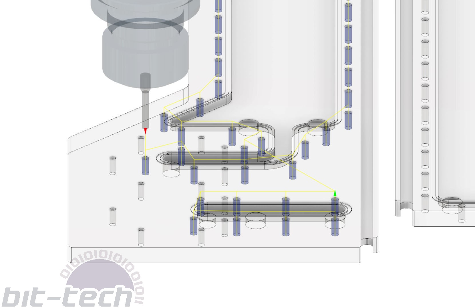
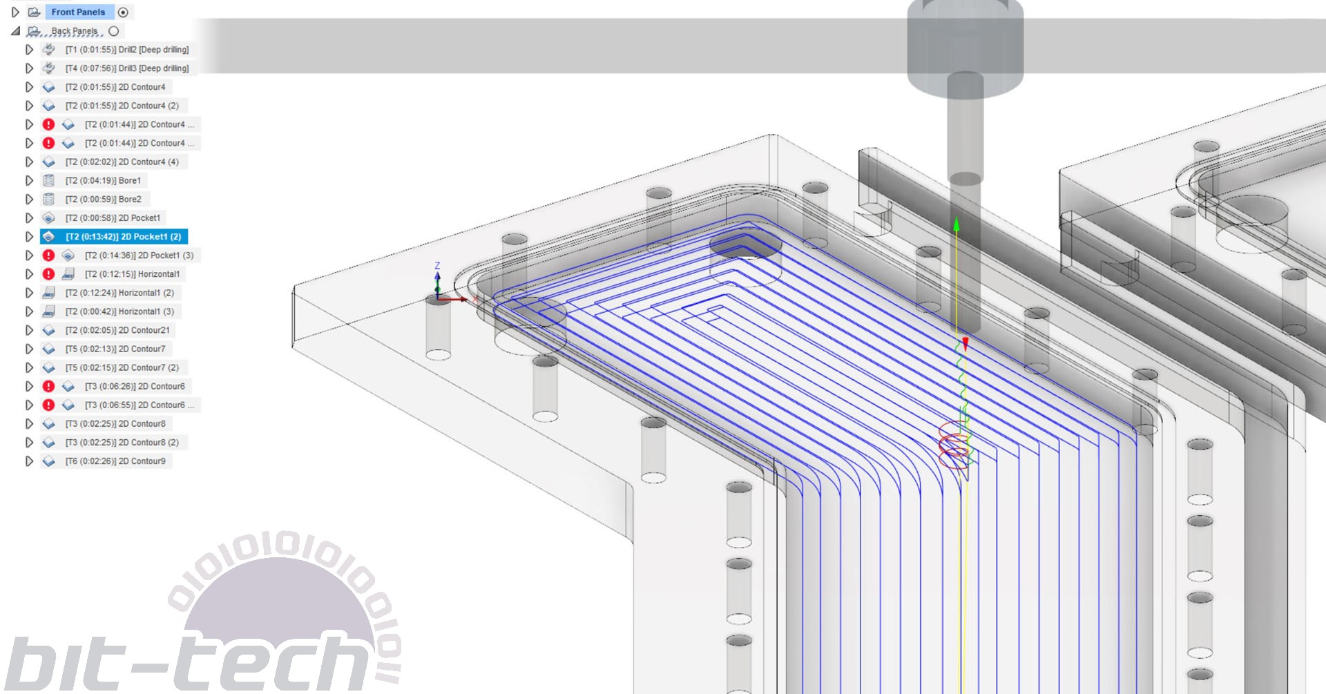
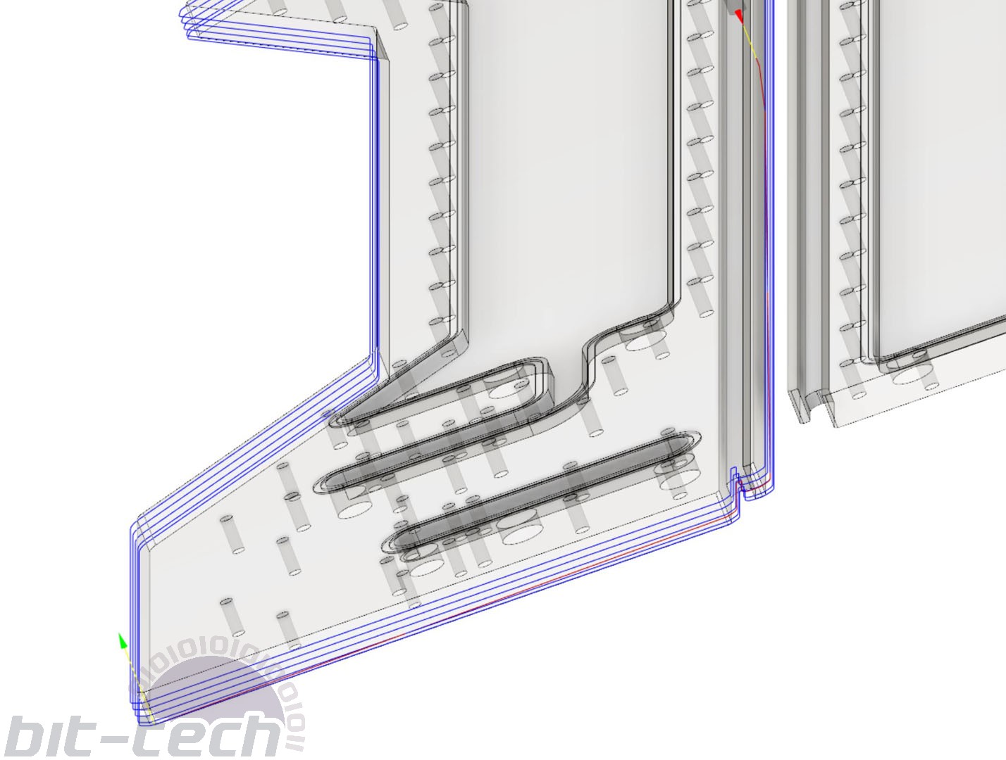
- Roughing cuts – For hogging out material you have a few different options. Personally, I like to use ‘2D Pocket’ rather than ‘2D Adaptive’ (same for 3D), as it allows my machine to be more rigid. Adaptive tool paths are high-tech and ensure constant tool loading and engagement, which is great for consistent tool wear and cutting at greater depths. The issue for me is that in distro plates, often large areas such as a reservoir will taper into a channel. Adaptive cuts work really well in larger areas, but as soon as the cut becomes narrower, it can send the tool path into a bit of a frenzy. Pocket cuts are more traditional and likely aren’t as good for the tool, but for the shapes I cut they’re gloriously efficient, and acrylic is a forgiving material compared with the metals that adaptive is really designed for.
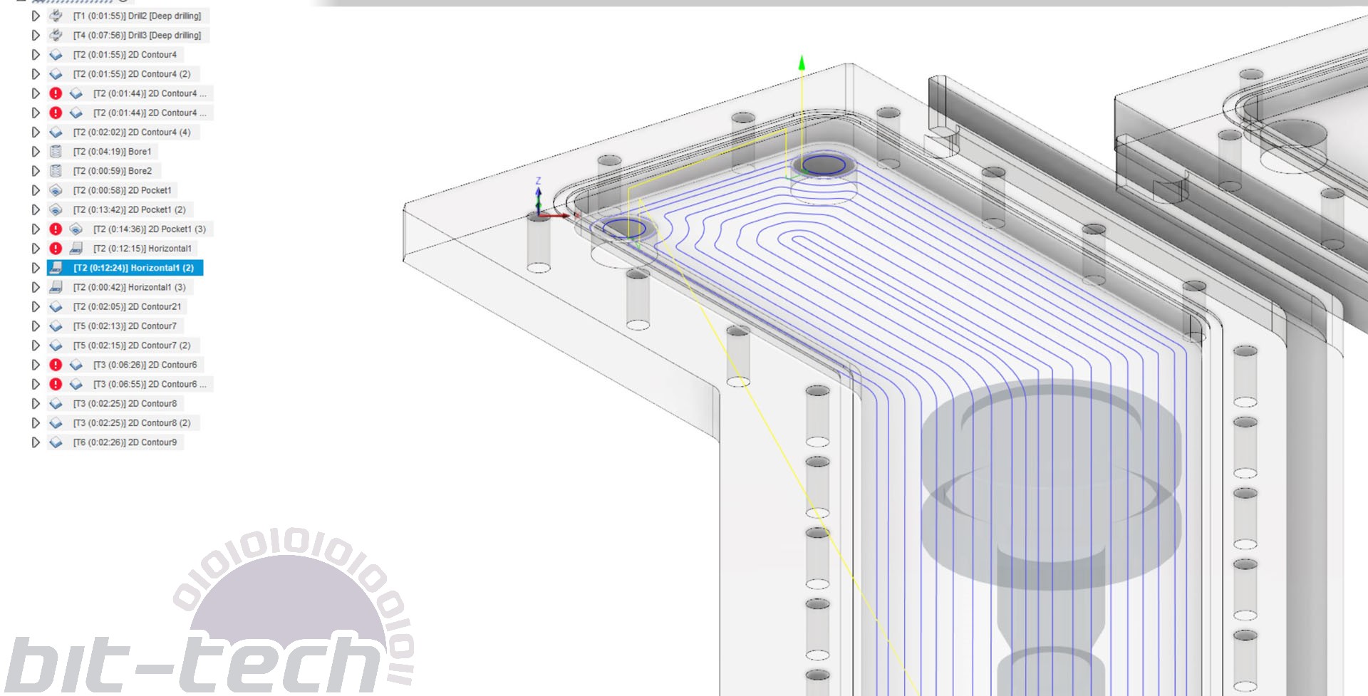
- Finishing passes – Finishing passes for acrylic can be very important for surface finishes. If you have a large area to cut, an adaptive or pocket toolpath will rarely leave a desirable result. 3D horizontal is a great finishing operation; it prevents sharp 90° corners within the path, which in turn prevents inconsistent surfaces from the spindle accelerating/changing direction suddenly. For finishing the side walls, use stock to leave to ensure you don’t leave a witness mark on the base of the cut.
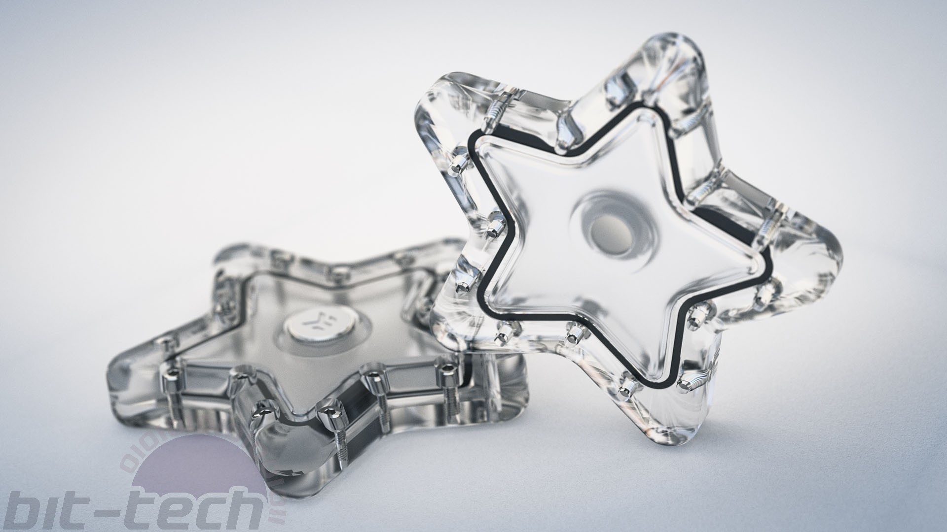
- Cut O-rings in two passes – I like to do an initial pass of 0.5mm depth, followed by a full depth cut that I’ve adjusted for the material. Because acrylic isn’t flat, you can’t just go in at full depth unless you first surface the whole material. To get around this, I measure the depth of the 0.5mm groove around the plate, then change the depth of cut for the next operation. If, for instance, one section was 0.6mm deep and another 0.4mm, I would do the next cut at 0.8mm so that the deepest part is 1.4mm in total. The worst thing you can do is go in at full depth without measuring, as you may not be able to compress the o-ring enough to achieve a tight seal if it cuts too deep!
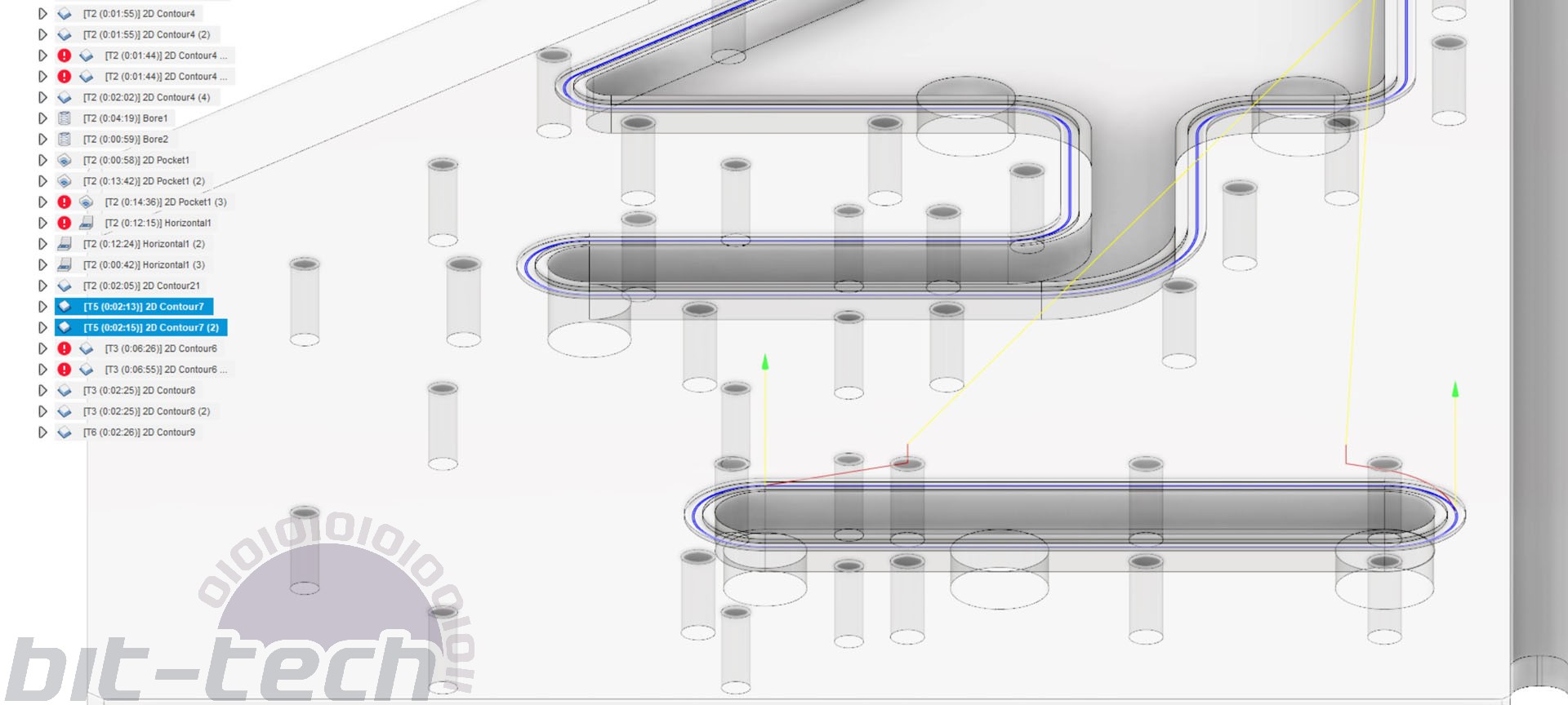
- Use multiple 2D contours when parting – This one’s another quality of life choice that really helps me out. When cutting all the way through a piece of acrylic, I use a 2D contour with a ramp and 3mm depth of cut; this tends to keep my machine happy. I also use a horizontal stock to leave of 0.2mm and axial stock to leave of 1mm. I then do another pass with the same 1mm axial stock to leave but 0mm horizontal value, followed by another at 0.4mm axial and then finally 0mm. This sounds a bit overkill, but what it does is ensure material rigidity for as long as possible. Having the 1mm of material at the bottom allows the finish cut to be well supported, resulting in a crystal-clear cut. The two subsequent passes just keep lateral forces to a minimum for the same reason.
- Experiment with speeds and feeds – One thing that I have found a little frustrating is having to experiment so much to find the optimal cutting settings for my setup. The main issue is that my machine simply isn’t rigid nor powerful compared with the sort of machines the tooling is designed for, and as such the manufacturer guidelines don’t really work so well. For the most part the tools are designed to run much faster and harder than I can realistically manage, so with that knowledge I’ve essentially just been bumping up my cutting feed rates over time until I reach machine hard limits. I’ve found that for my machine, cutting over 1800mm/min introduces chatter when changing direction suddenly. The values in the video are likely far more conservative than what I use now, largely down to continuing to optimise and improve my machine.
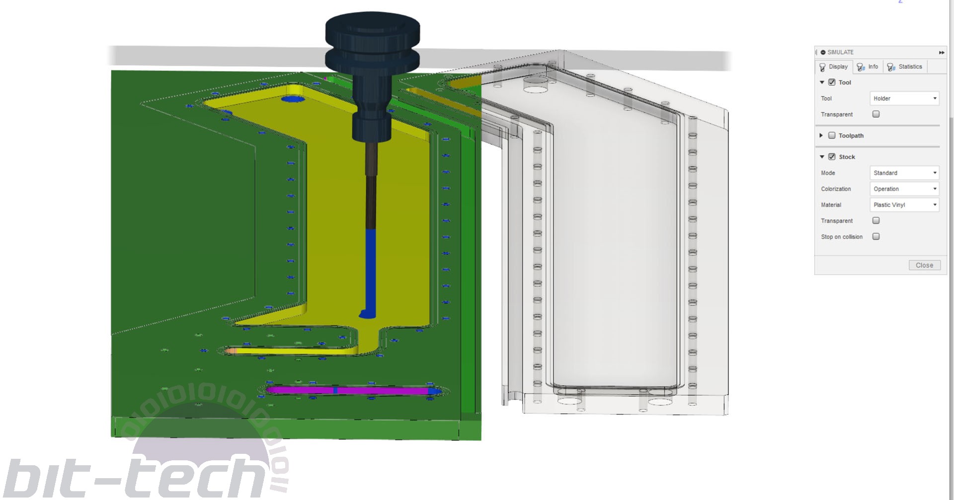
- SIMULATE YOUR CUTS – Honestly, this step is just so essential. The number of times where I’ve noticed an error in my toolpaths thanks to the simulation makes it abundantly clear how useful this step can be. It’s significantly quicker and cheaper to just watch through the simulation a couple times thoroughly, than to cut, fail, then re-cut a part.
Machining
At this point it’s more a case of carrying out the motions that were set up in the previous sections. Assuming your toolpaths are all ready and that you’ve sorted out your workholding, it’s a case of double checking everything and being thorough.
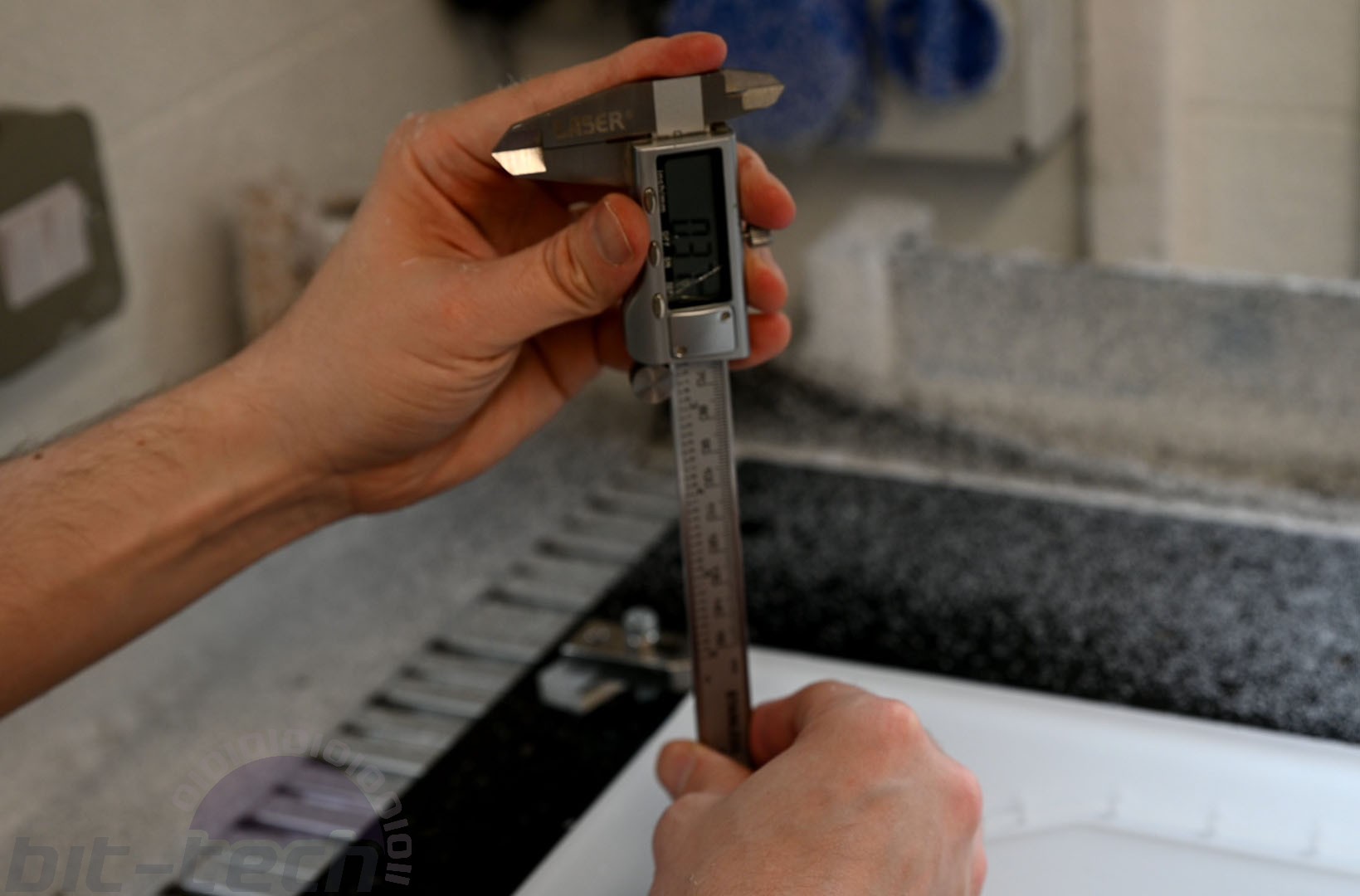
As I mentioned above, for the O-rings it’s important to adjust the cutting depth to match the surface of the material, else you risk cutting a channel that’s too deep to maintain the correct O-ring compression ratio.
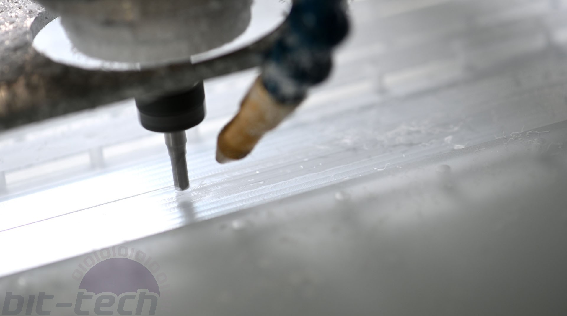
The other major point is to keep air blowing on the cutter! Whilst you can indeed cut acrylic without a coolant system going, having at the very least air running over the tool helps to clear chips from the cut. I like to use coolant in addition, as I find it helps with achieving clearer finishes straight off the machine. I use Shell Fenella combined with a Noga minimal coolant system for this, set to 130PSI.
Final words
Hopefully this monster of a text piece has been handy! Machining a distro plate is honestly a fairly simple job once you’ve got behind the basics. I’d love to see what everybody’s able to come up with! To aid that, I’m going to be uploading a fun challenge piece in the coming weeks that should prove to be an interesting task - reckon you’ve got what it takes?
RELATED ARTICLES


MSI MPG Velox 100R Chassis Review
October 14 2021 | 15:04

Want to comment? Please log in.