In this video, I briefly go over how a pinout diagram works and why you really want to be using one if you fancy making a set of custom cables for your PC.
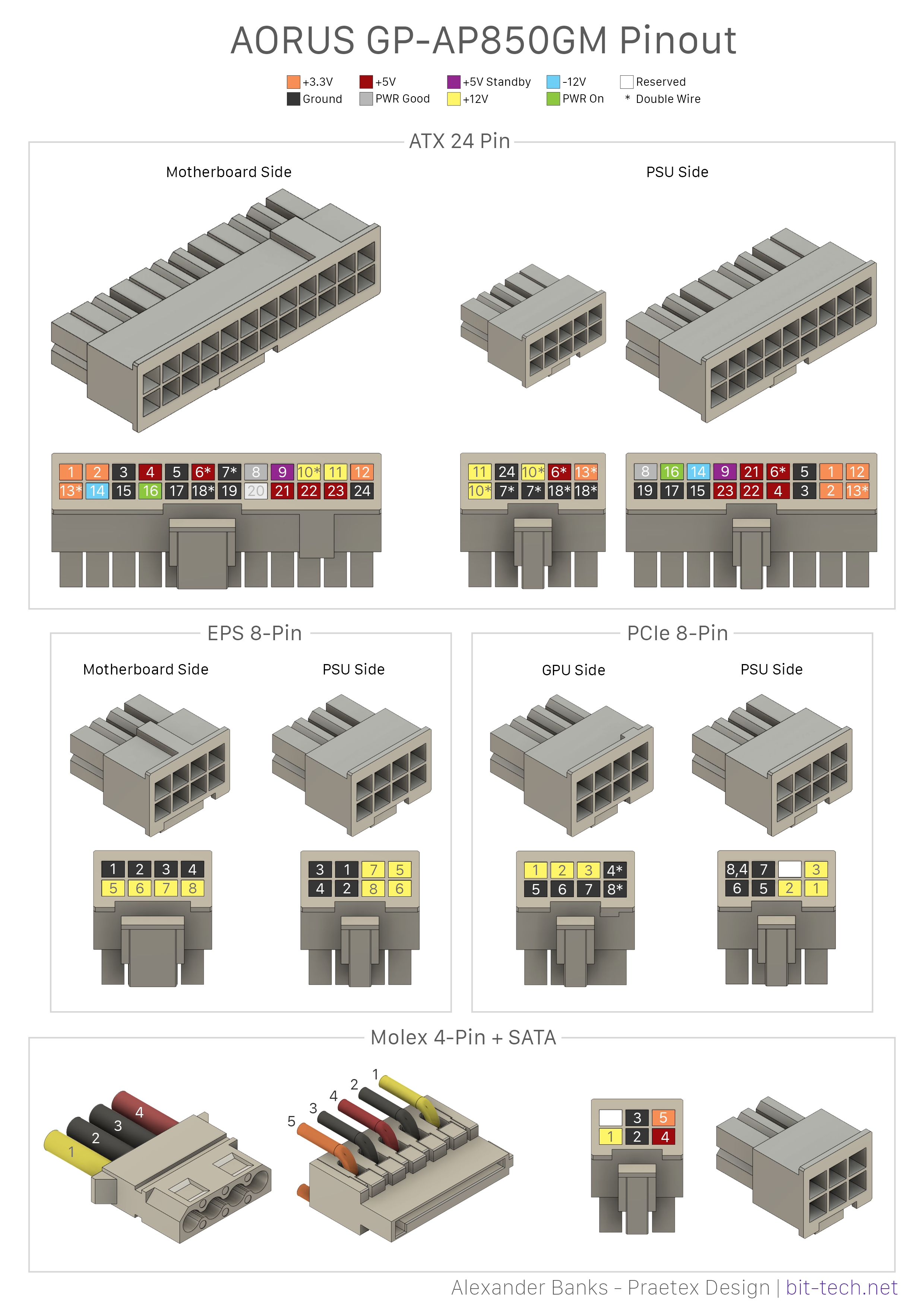
Additionally, if you'd like to use the pinout template I made, feel free to download it from GrabCAD above. Not only have I uploaded a .PSD document of the template file, but I also included a copy of the Fusion 360 connector generator that I use to make the connectors themselves. If you're looking to download one of the diagrams, I also have the full resolution versions of the following two pinout diagrams for:
Aorus GP-AP850GM
Corsair Type 4 Gen 3 - RMx/RMi/SF Series Units
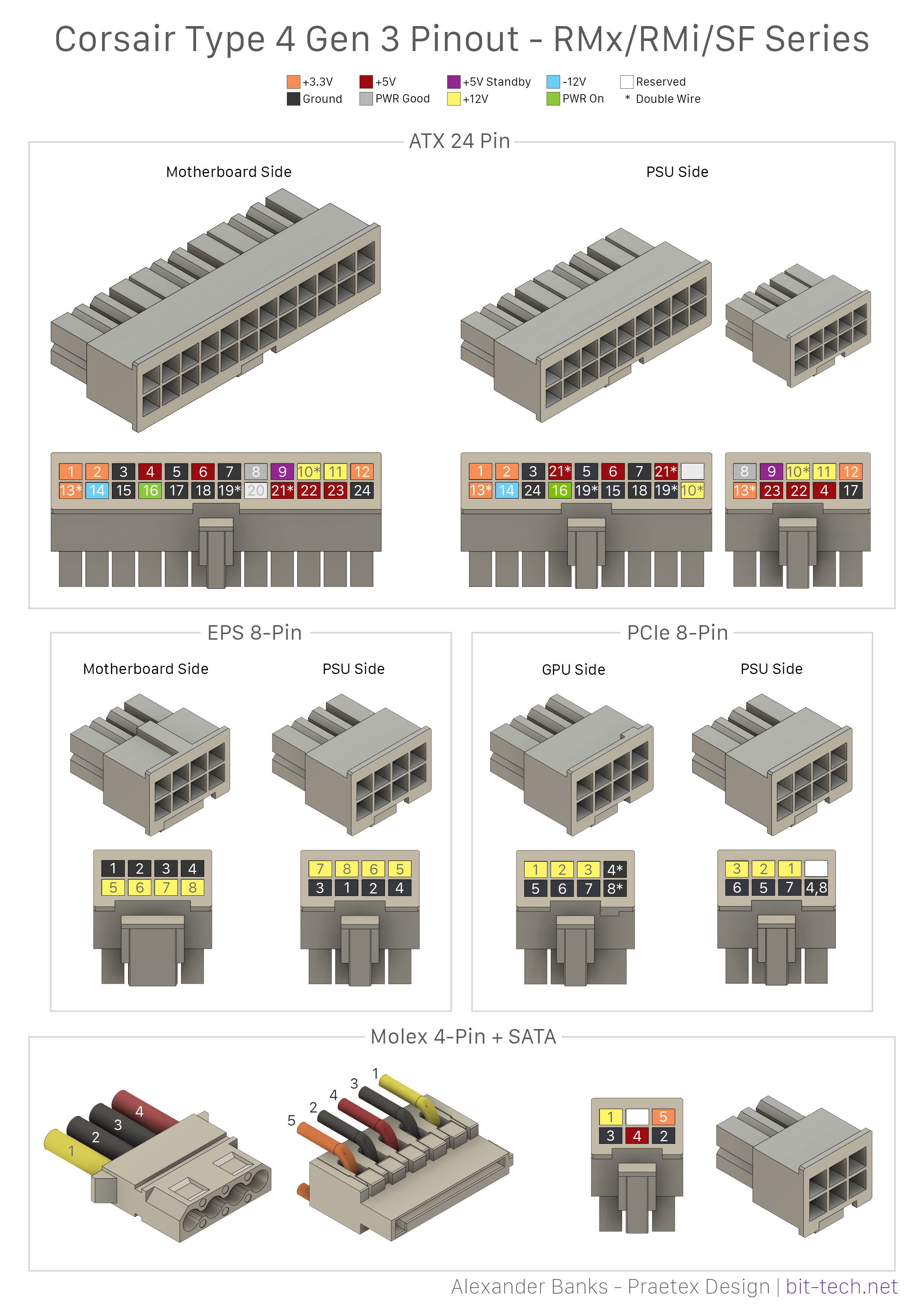
If you want to check which version your Corsair power supply is, head over to their compatibility page, which should show which pinout layout is required. When making your own cables, it's always wise to have to hand a power supply tester and/or a multimeter so that you can double and then triple check every connection.
RELATED ARTICLES


MSI MPG Velox 100R Chassis Review
October 14 2021 | 15:04

Want to comment? Please log in.