
A Knight in Shining LEDs
Okay, this circuit is really part of the "Knight Rider" project. I have separated it purely for the benefit of web search engines looking for a "Hard Drive Activity Meter". It uses the same basic circuit, circuit board designs and construction as before, and therefore I am not going to repeat all that detail. I strongly suggest you refer to the "Knight Rider" project for construction details.
This circuit is designed as a replacement for the standard HDD activity LED and offers an indication of the amount of activity by lighting a row of LEDs. The higher the HDD activity, the more LEDs light. It does not give a reading of actual Mb/s, just how hard the drive is working.
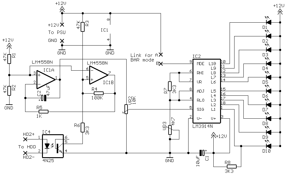
The circuit is based around the "Classic" Knight Rider design and differs only with R3 being fitted in it's alternate position, the addition of IC4 and R6, and VR1 is replaced with a wire link.
The opto-isolator, IC4, connects to the HDD LED header on the motherboard and serves to isolate the circuit from the rest of the system whilst ensuring compatibility with just about every motherboard that has a HDD LED. As the HDD reads and writes it produces a stream of pulses which are fed to the circuit via the opto-isolator. These pulses are fed into IC1b, which buffers and shapes these pulses before feeding them into IC1a. IC1a is an integrator whose job it is to "smooth" these pulses into a voltage level. This voltage is reasonably proportional to the frequency and duration of the pulses generated by the HDDs activity. Hence, the busier the drive, the higher the voltage. This voltage is fed from the output of IC1a into IC2 which is an LED bargraph voltmeter. So in a nutshell, the busier the drive, the more LEDs light up. Similar to the previous circuits, the display can be operated in either DOT or BAR mode and has 10 and 20 LED variations.
VR3 sets the "zero" and is adjusted so that all the LEDs are just extinguished with no HDD activity. VR2 is the "span" and is adjusted so that all the LEDs are lit during heavy or constant drive activity. This span adjustment is somewhat subjective and is found by trial and error during HDD activity.
Parts List with order codes for UK and US suppliers
Component layout - top view (left) and Track layout - Viewed from above (right)
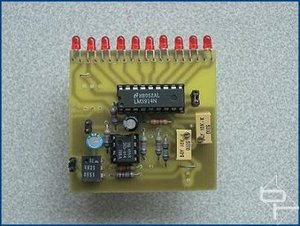
The finished board.
Component layout - top view (left) and Track layout - Viewed from above (right)
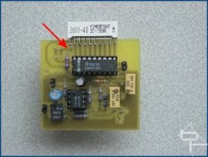
The finished board and the detail of how the anodes are linked together and connected to the board using pad13, indicated by the red arrow.
Okay, this circuit is really part of the "Knight Rider" project. I have separated it purely for the benefit of web search engines looking for a "Hard Drive Activity Meter". It uses the same basic circuit, circuit board designs and construction as before, and therefore I am not going to repeat all that detail. I strongly suggest you refer to the "Knight Rider" project for construction details.
This circuit is designed as a replacement for the standard HDD activity LED and offers an indication of the amount of activity by lighting a row of LEDs. The higher the HDD activity, the more LEDs light. It does not give a reading of actual Mb/s, just how hard the drive is working.
The circuit is based around the "Classic" Knight Rider design and differs only with R3 being fitted in it's alternate position, the addition of IC4 and R6, and VR1 is replaced with a wire link.
The opto-isolator, IC4, connects to the HDD LED header on the motherboard and serves to isolate the circuit from the rest of the system whilst ensuring compatibility with just about every motherboard that has a HDD LED. As the HDD reads and writes it produces a stream of pulses which are fed to the circuit via the opto-isolator. These pulses are fed into IC1b, which buffers and shapes these pulses before feeding them into IC1a. IC1a is an integrator whose job it is to "smooth" these pulses into a voltage level. This voltage is reasonably proportional to the frequency and duration of the pulses generated by the HDDs activity. Hence, the busier the drive, the higher the voltage. This voltage is fed from the output of IC1a into IC2 which is an LED bargraph voltmeter. So in a nutshell, the busier the drive, the more LEDs light up. Similar to the previous circuits, the display can be operated in either DOT or BAR mode and has 10 and 20 LED variations.
VR3 sets the "zero" and is adjusted so that all the LEDs are just extinguished with no HDD activity. VR2 is the "span" and is adjusted so that all the LEDs are lit during heavy or constant drive activity. This span adjustment is somewhat subjective and is found by trial and error during HDD activity.
Parts List with order codes for UK and US suppliers
10 individual LED version
This board design like the others following, uses R3 in it's alternate position and has additional components IC4 and R6. VR1 is also replaced with a wire link. These changes to the layout are denoted in red. This board has two links, one of which replaces VR1. 
Component layout - top view (left) and Track layout - Viewed from above (right)
The finished board.
Single LED array version
Note the two links on the circuit board and that R3 is fitted in it's "alternate" position. 
Component layout - top view (left) and Track layout - Viewed from above (right)
The finished board and the detail of how the anodes are linked together and connected to the board using pad13, indicated by the red arrow.
RELATED ARTICLES


MSI MPG Velox 100R Chassis Review
October 14 2021 | 15:04

Want to comment? Please log in.