This article may contain affiliate links. If you make a purchase we may receive a commission that helps support this site.
Link to Downloadable Files
The Basics
Rather than use the CNC or another automated process, it made sense to go back to basics to demonstrate how making a motherboard mounting tray itself is simple. Obviously the most basic way is just to plonk your board down, mark where the holes are and get cutting. This method though doesn't allow any means of planning ahead, not so good if you're making quite a few panels and want them all to slot together neatly later.
So to that end, I'm using a paper template. I showed how to make these templates earlier in this article on the subject. This template in particular is the PDF one linked above for ATX motherboards.
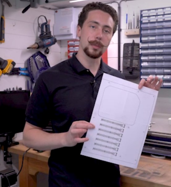
For ease of demonstration, I'm using some MDF to act as the mounting board itself, I'd normally use a plastic-like acrylic or a metal-like aluminium. After masking off a section (so that the template can easily be removed later) I used some spray adhesive to attach it in a position I liked. I've used one flat edge to act as a guide for the template, that way the I/O section of the motherboard lines up with the edge of the plate nicely.
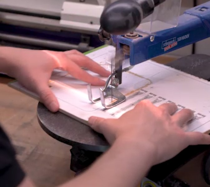
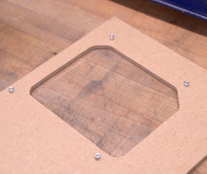
After that it was just a matter of cutting it out with a jigsaw and a scroll saw (for the internal cutout section) and then cleaning up the edges with files. The actual shape of the tray doesn't really matter, I've made it a bit oversized so that it can be seen more easily. Choose what fits for your mod, there aren't really any rules here, the only important bit is where the mounting holes are.
The Specifics
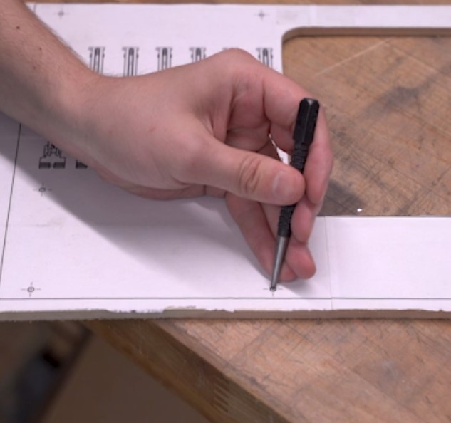
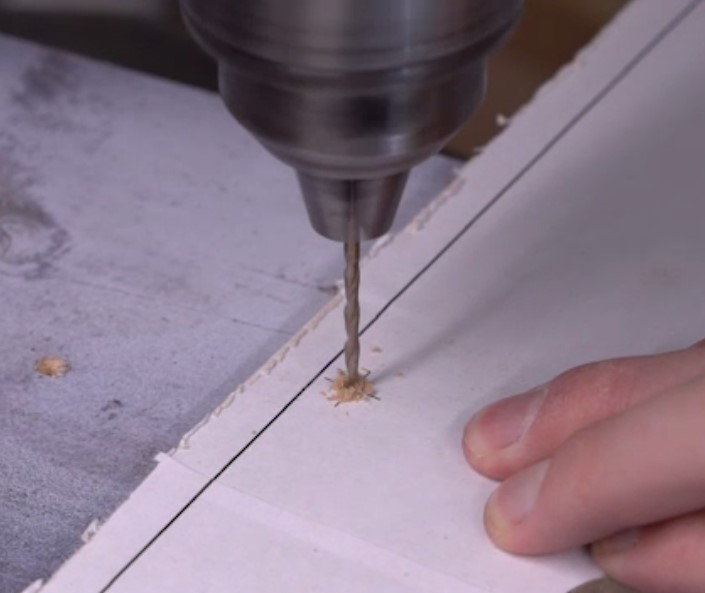
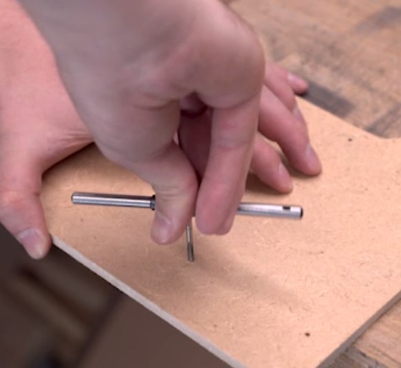
With the tray cut, here comes the important bit: drilling the holes. The templates are great for this as they're accurate and easy to work with. Using a centre punch I marked the hole locations and then drilled. You naturally have some leeway with these, but being as accurate as you can always helps. Since I have access to a load of M3 standoffs for later, I'm drilling 2.5mm holes and tapping for M3 screws.
Yeah I know MDF is rubbish for tapping, especially small thread sizes like M3. For a real build, use threaded inserts for this, or a more hardy material. You can also use 6/32 standoffs like found in most cases or M4 ones.

For that matter, standoffs are your friends. Obviously they serve the role of lifting your board from the tray, which is handy not only if working with conductive materials, but because motherboards nowadays just have so much stuff on the back of them. I tend to use standoffs (either 5mm or 8mm) even in builds where I can machine them into the tray, just because it makes it easy to ensure clearance.
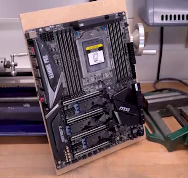
Install your standoffs and you're good to go; there really isn't anything more to it for this basic component. Using a template from a CAD file means you can easily now locate the places for the I/O cutout or for PCIe brackets, etc. It gives you a handy frame of reference, from which to add the more complex bits. The I/O cutouts and PCIe slots are all measured in relation to the motherboard PCB location, so knowing exactly where you put it makes this part a breeze in comparison to eyeballing it.


MSI MPG Velox 100R Chassis Review
October 14 2021 | 15:04

Want to comment? Please log in.