For a D5 the process is largely the same as with a DDC. As such I would thoroughly recommend looking through that page, as I'll be going a bit quicker with this one and focusing instead on the areas unique to this pump.
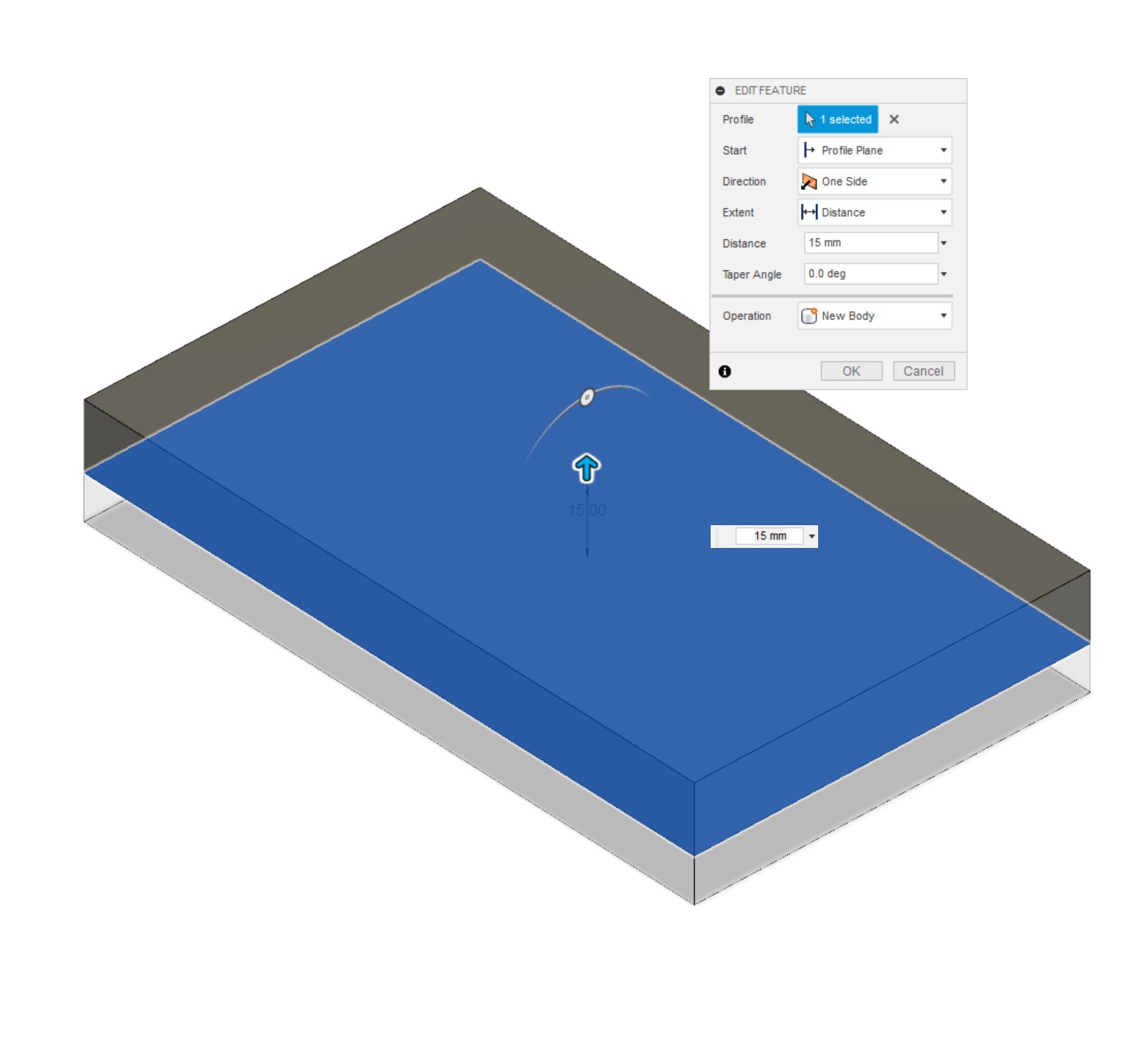
Like we did for the DDC, create a 90x150x10mm thick plate in the centre of the workspace and label it 'Front Plate'. Now, instead of extruding another 10mm plate, this time we're going 15mm, again as a new component. This is because the D5 impeller protrudes much further than the D5, so requires thicker stock for machining. As I mentioned in the introduction, there are multiple ways of mounting these pumps: You can add them to thin plates if you use an adaptor of sorts, but we're integrating it directly, so it needs the thickness. Name this new piece 'Rear Plate'.
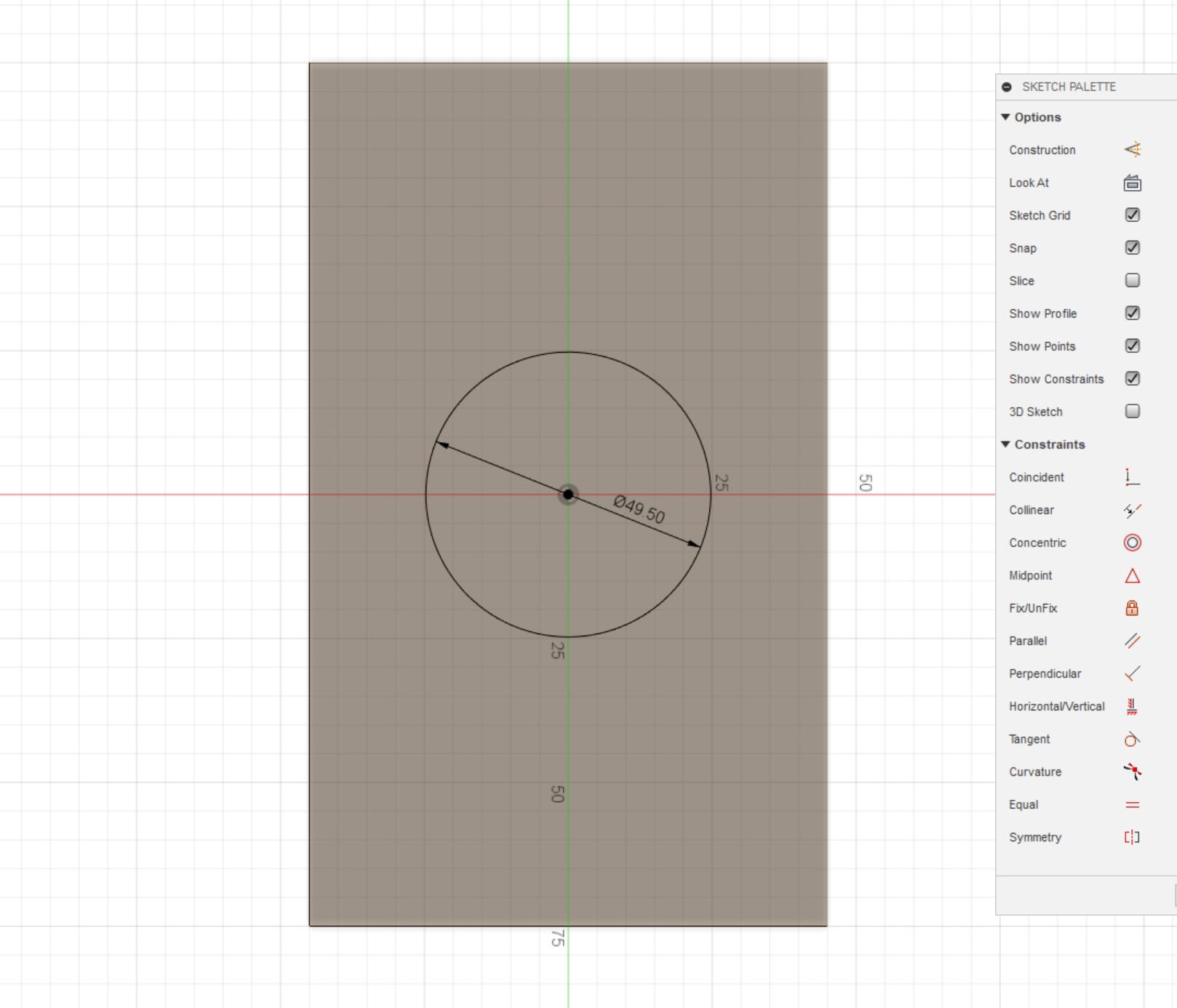
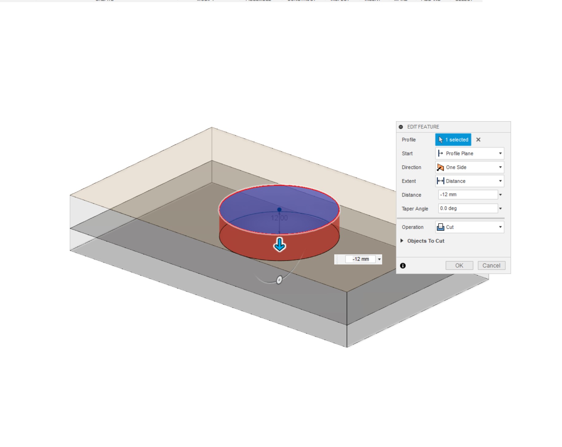
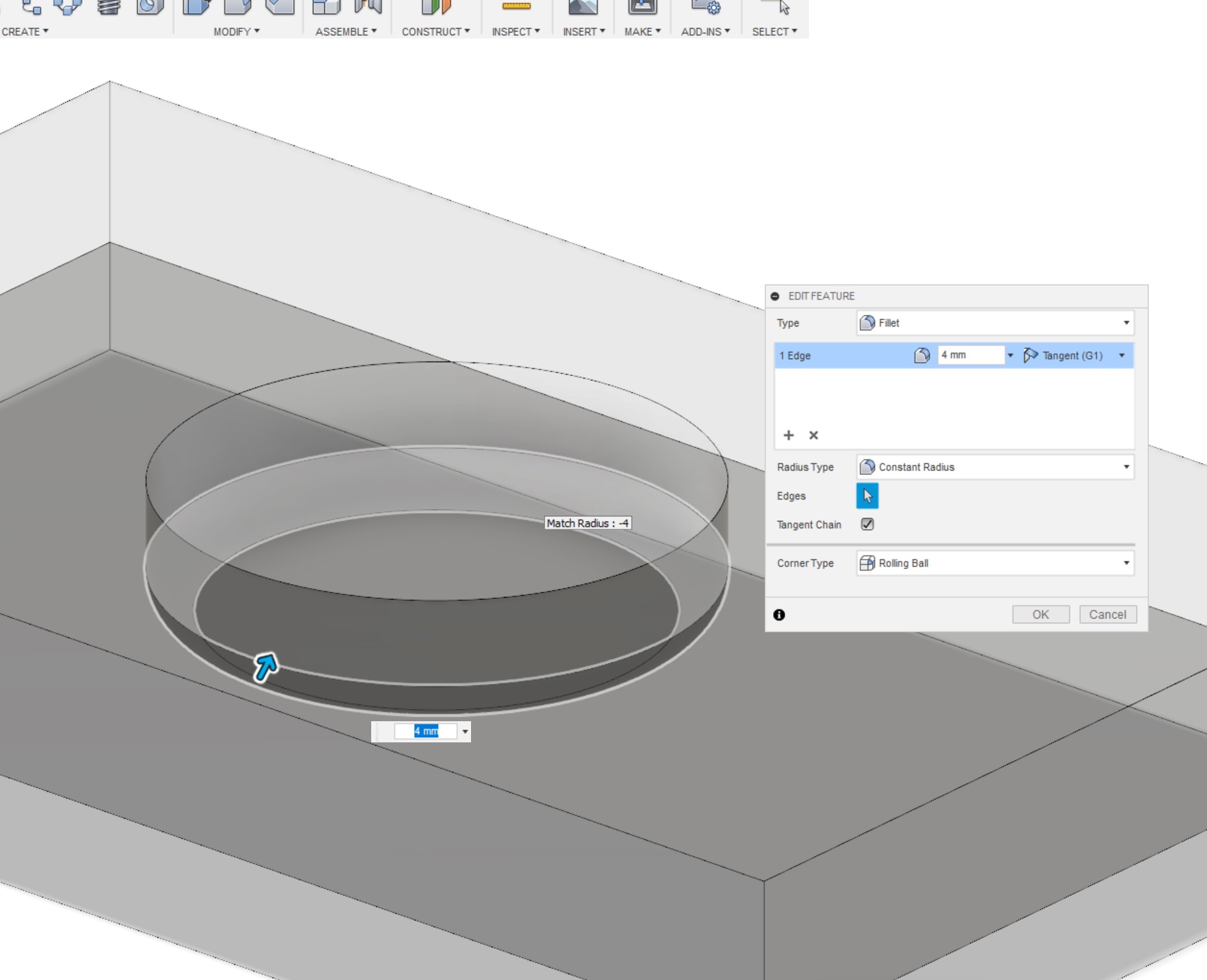
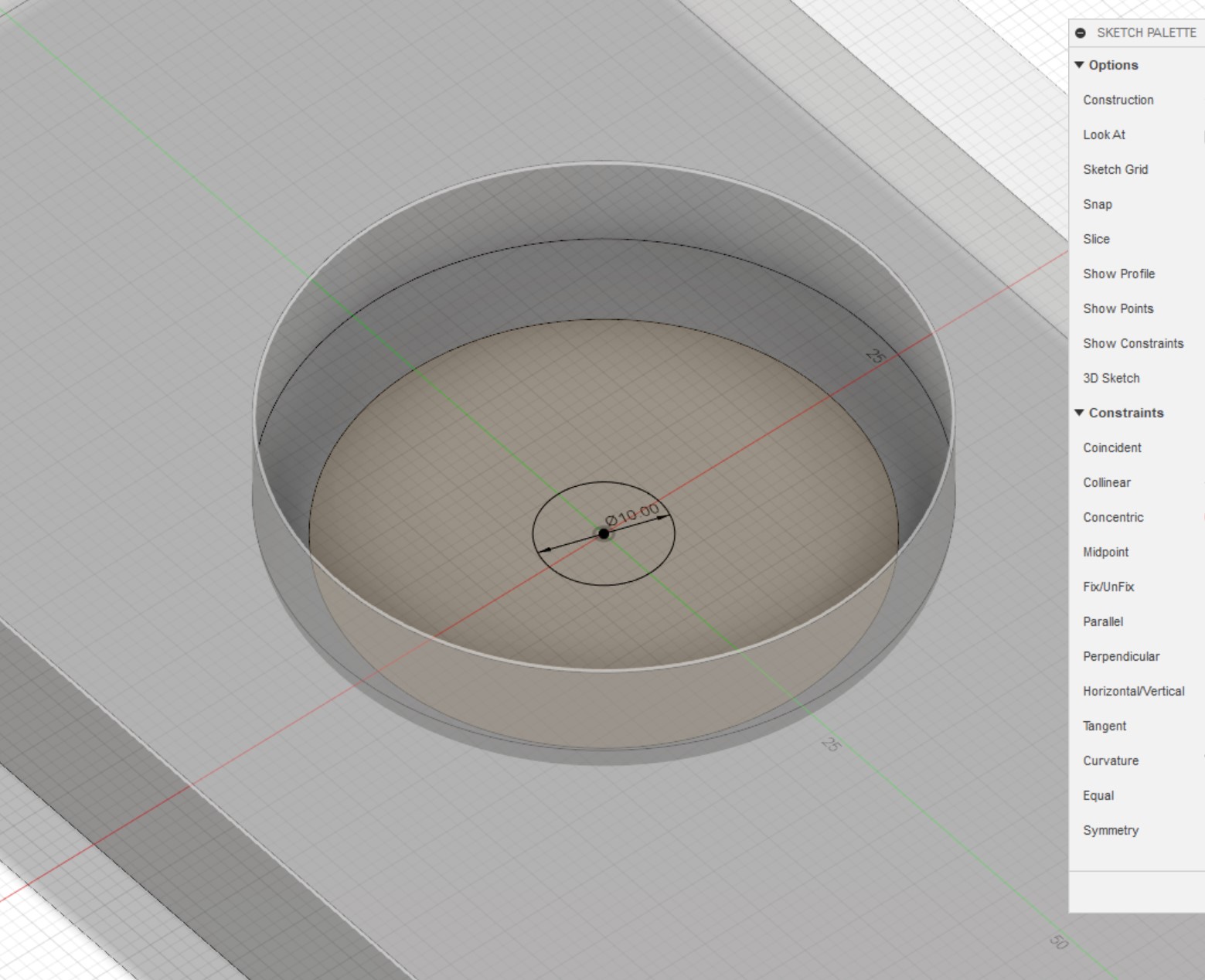
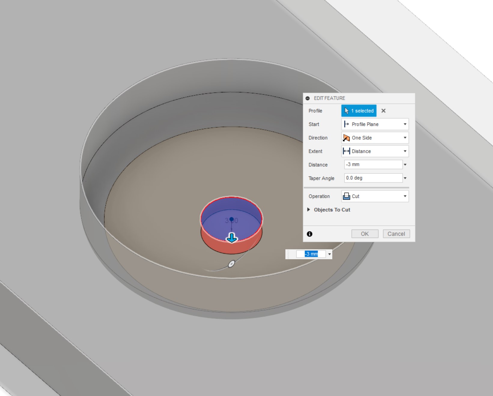
Starting with the pump cavity, draw a centred circle on the 'Rear Plate', this time 49.5mm in diameter. Exit and extrude this circle down 12mm to make the basic cavity. This time, add a 4mm fillet to the bottom edge of the cavity (also works with a 4mm chamfer instead). Create a new sketch on the base of the cavity and add a 10mm circle for the inlet. Extrude this circle 3mm downwards into the material to complete the inlet.
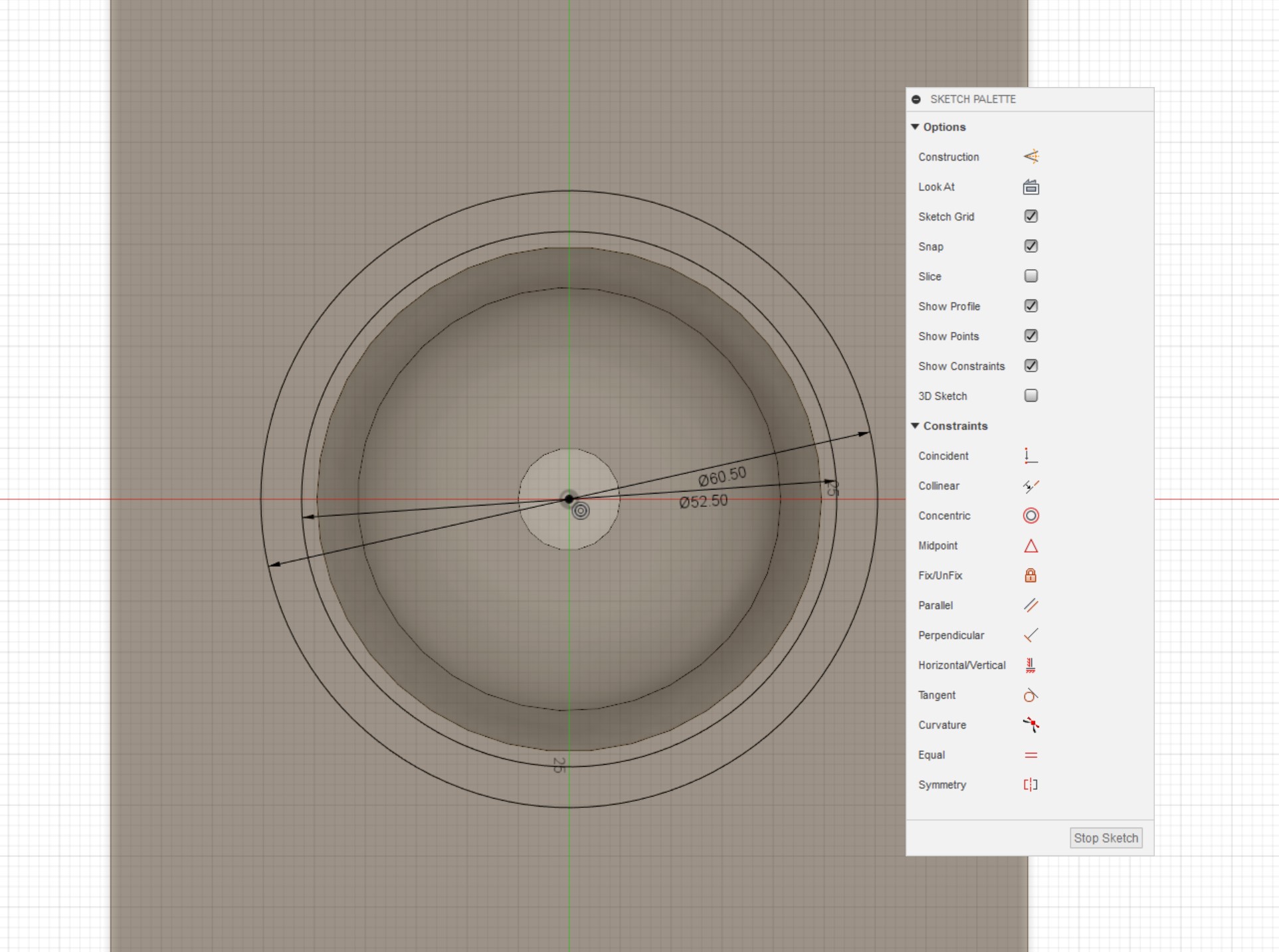
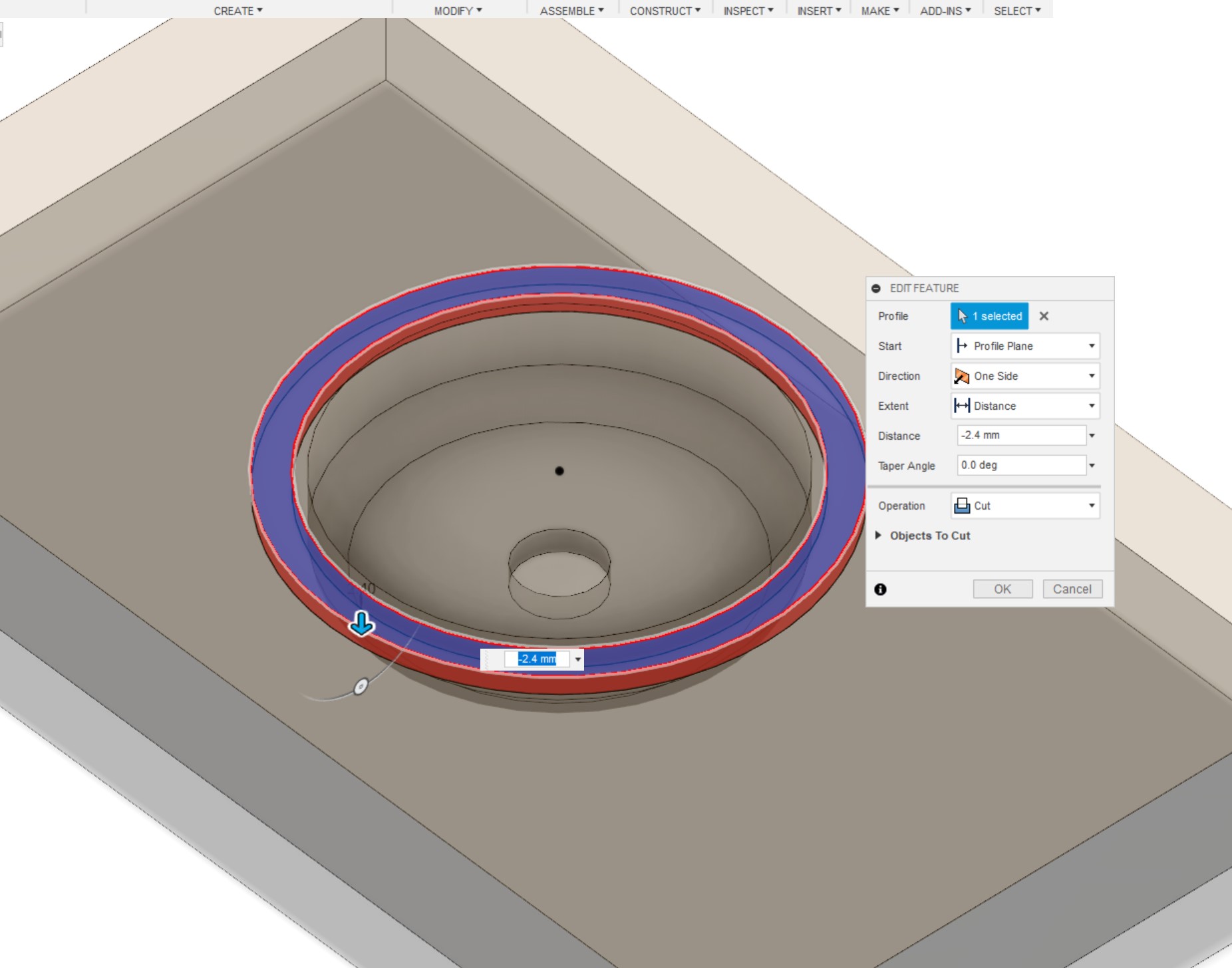
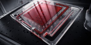
Next up we need to make the O-ring for the pump top. This is what creates the watertight seal between the face of the pump and the distro plate. Create a new sketch on the 'Rear Plate', then add a circle of 52.5mm diameter, using the same centre point as the inlet, then add another of diameter 60.5mm. This is the channel size I use for the O-rings in my pump tops, but make sure to double check yours as they might be different! Exit the sketch, and extrude this ring 2.4mm downwards into the material.
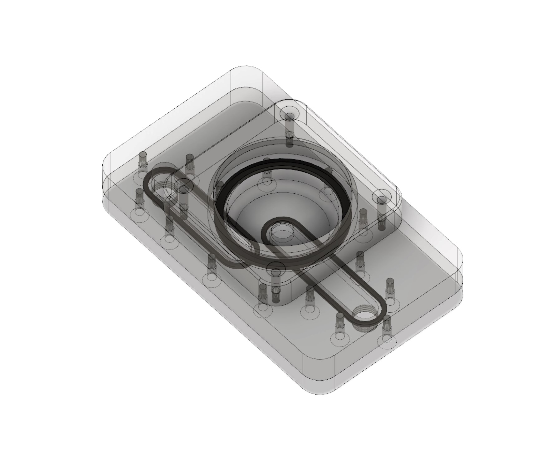
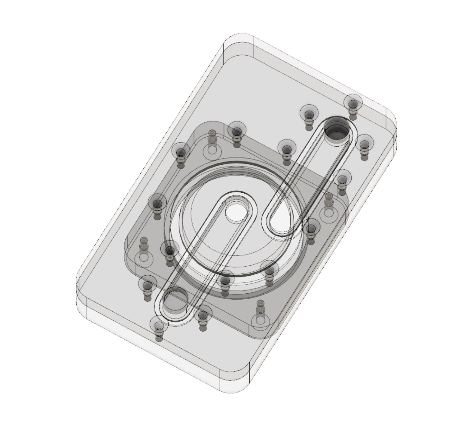
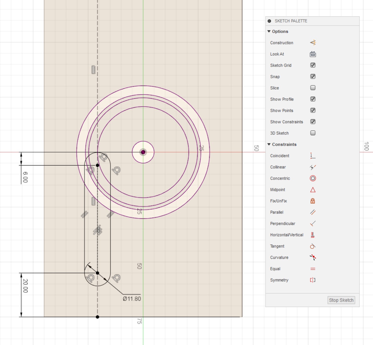
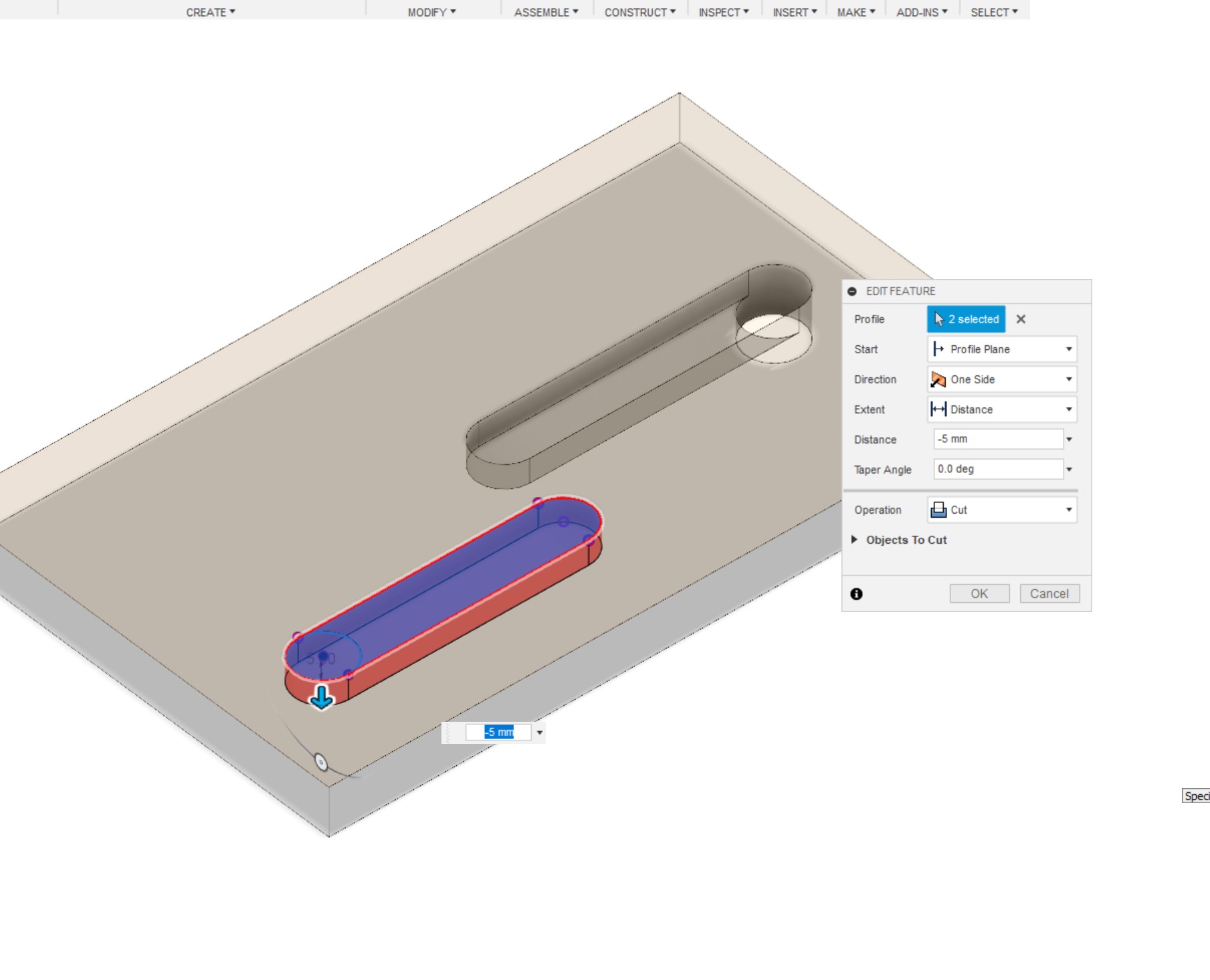
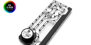
Since we're in control of the mounting mechanism this time round, I find it easier to draw in the channels next. It's exactly the same process as with the DDC pump, only different numbers. Again start with the outlet channel on the 'Rear Plate', draw a slot of 11.8mm width, place one end 20mm away from the bottom edge, and place the other end 6mm below the centre point of the workpiece. Draw a construction line from the edge of the 4mm fillet down to the end of the workpiece, constrain the line so that it's tangential to the fillet circle and is also vertical. Now constrain the slot so that the centre-line is collinear to that construction line. Exit and extrude the channel we just drew 8-10mm into the workpiece, again it will cut into the pump cavity and provide a route for the coolant to flow. On the 'Front Plate', project the outlet channel and the the pump inlet, then draw in your desired pump inlet channel, extrude both of these 5mm into the workpiece. Add the O-rings into the the front plate following the method listed in the Distro Plate article, namely an offset of 1.5mm and a channel width of 2.2mm, extruding to a depth of 1.2mm.
The reason for modelling the channels for the distro before doing the bracket is that you can freely move the screws around on the bracket and change the shape to match your design. For the 1000D I made use of this to create three different bracket shapes so that I could place the pumps near to one another.
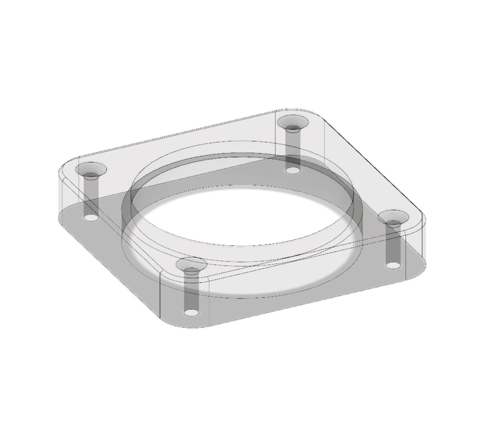
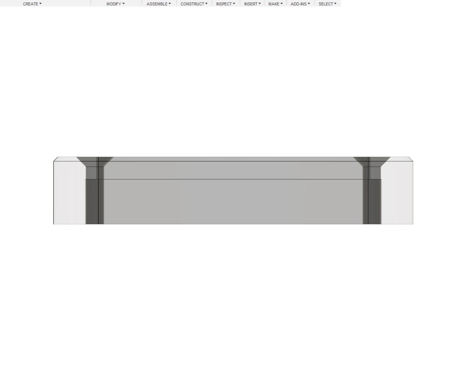
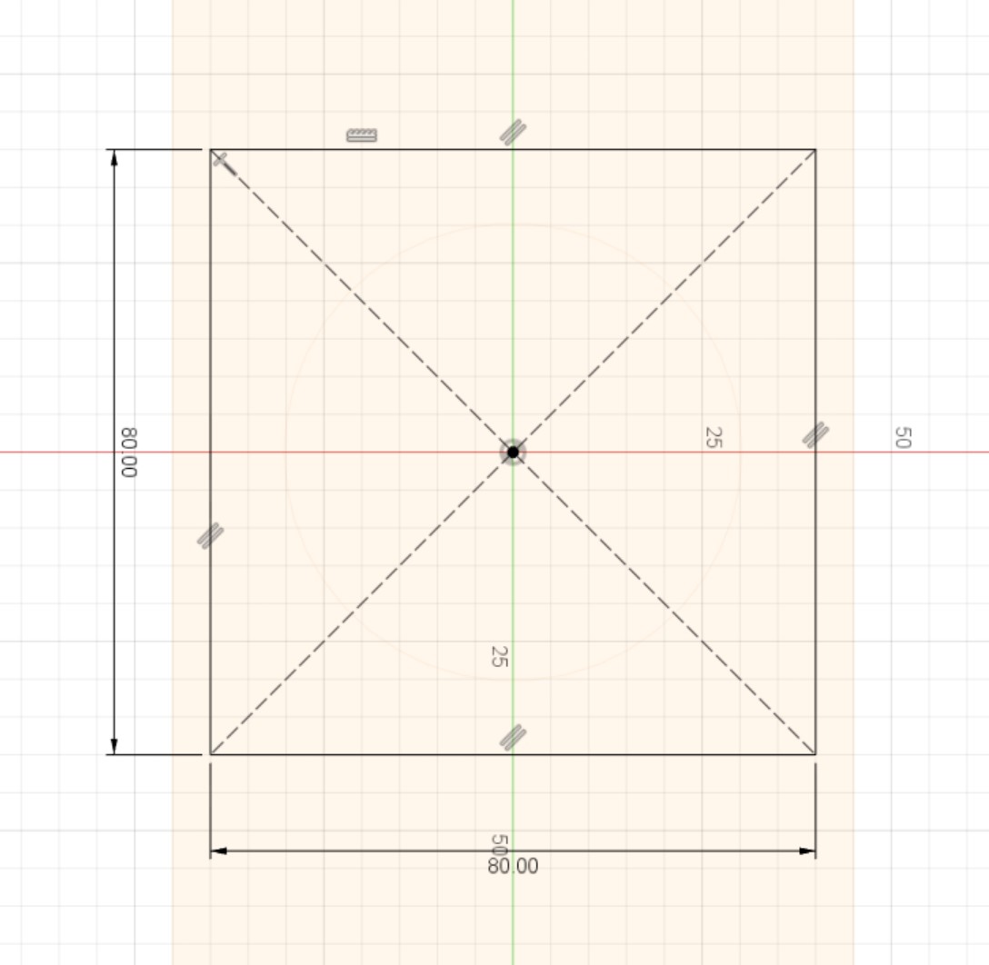
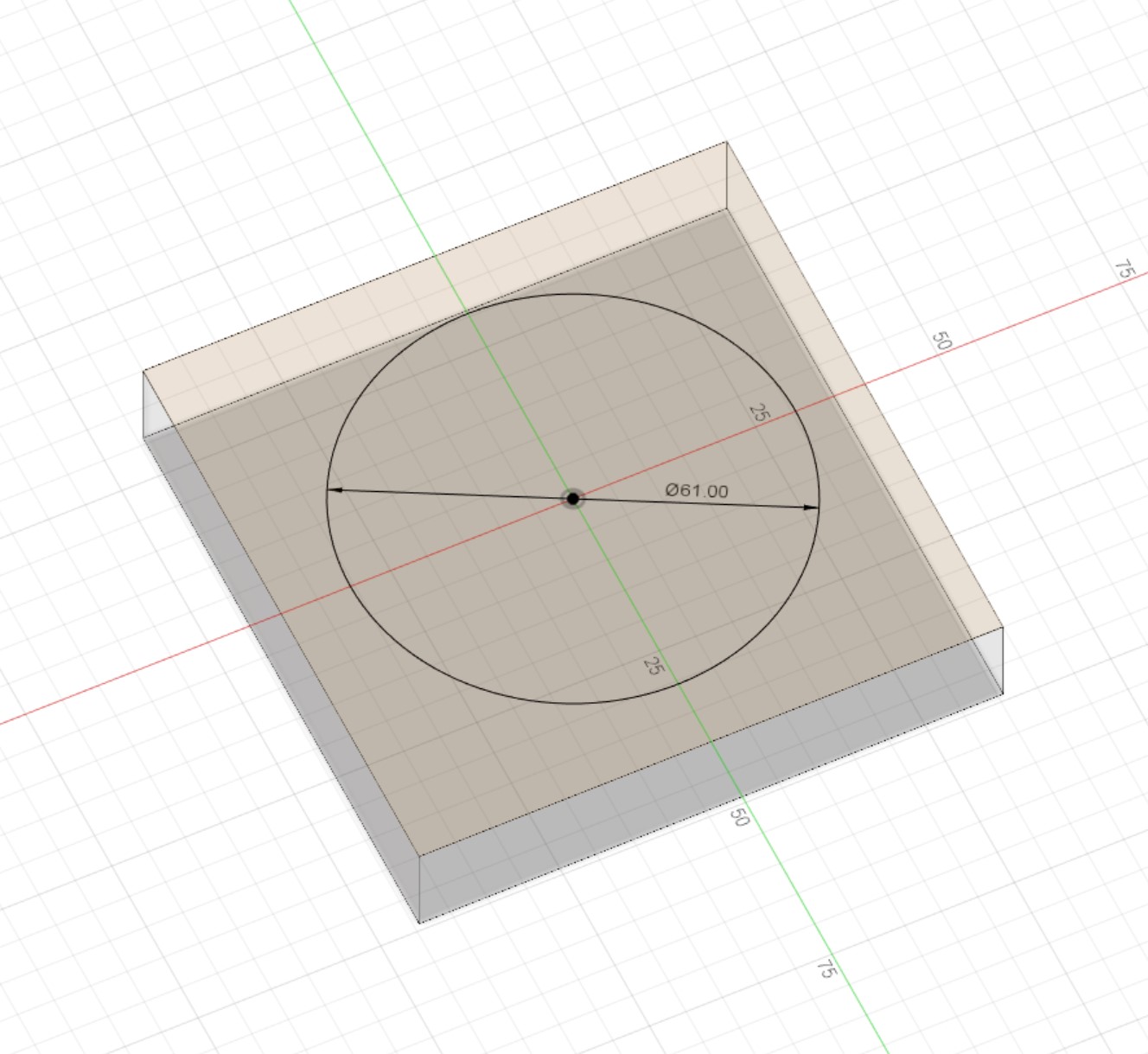
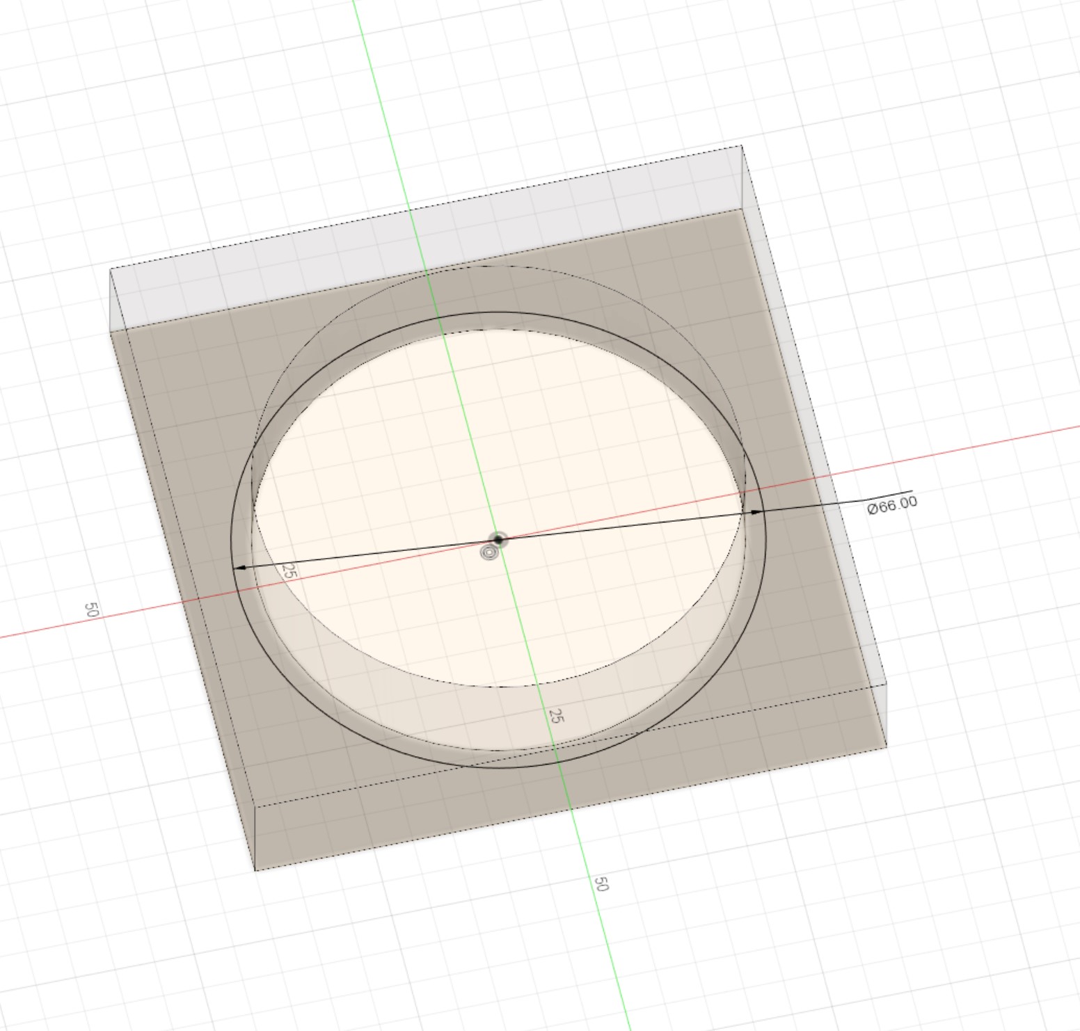
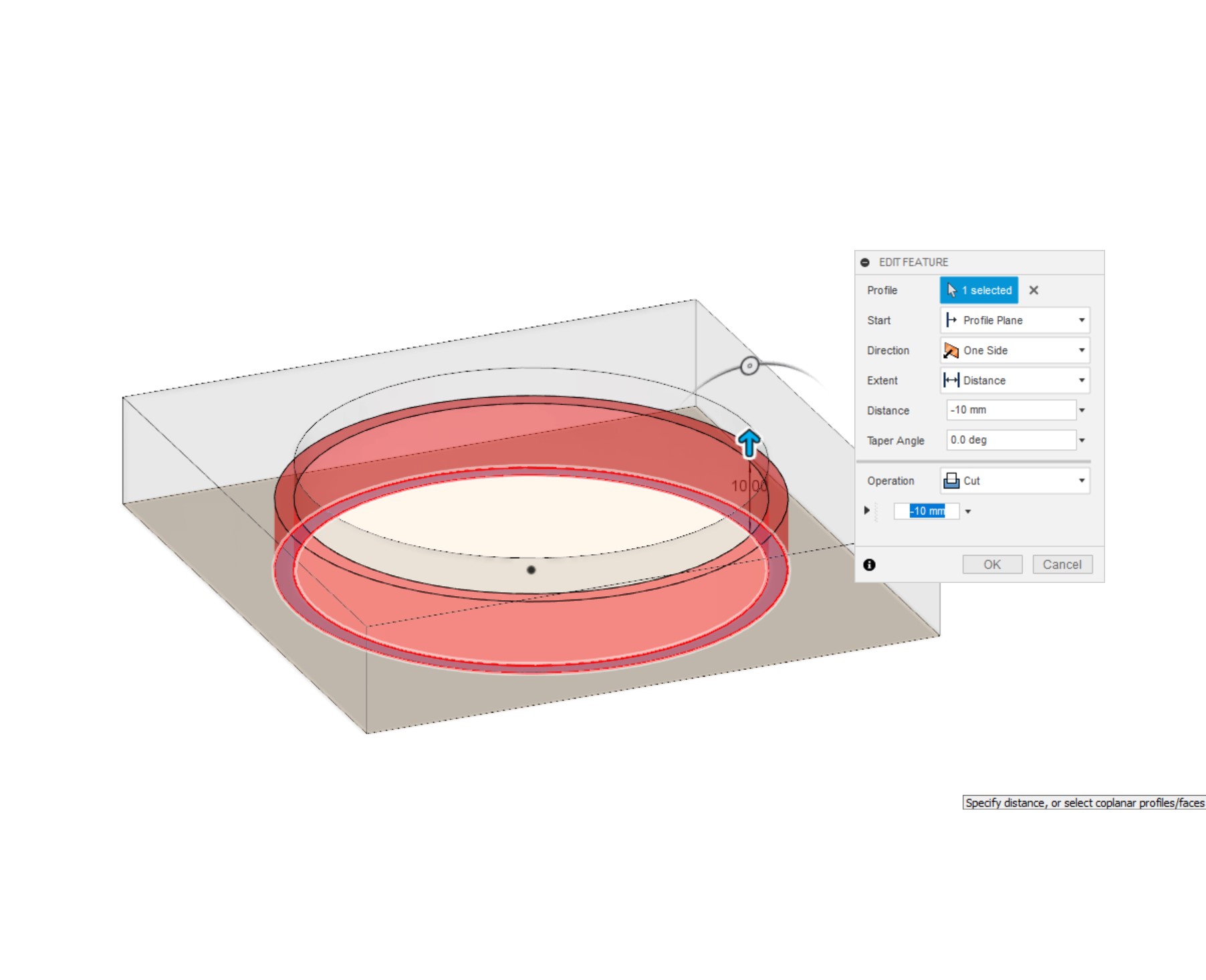
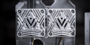
The bracket design I like to use is very simple indeed. The basic version is a square 80x80x15mm, in the centre is a through hole of 61mm in diameter (this allows the pump body to slide through). The clamping is provided by a larger 66mm diameter hole on the other side that's extruded 10mm into the bracket.
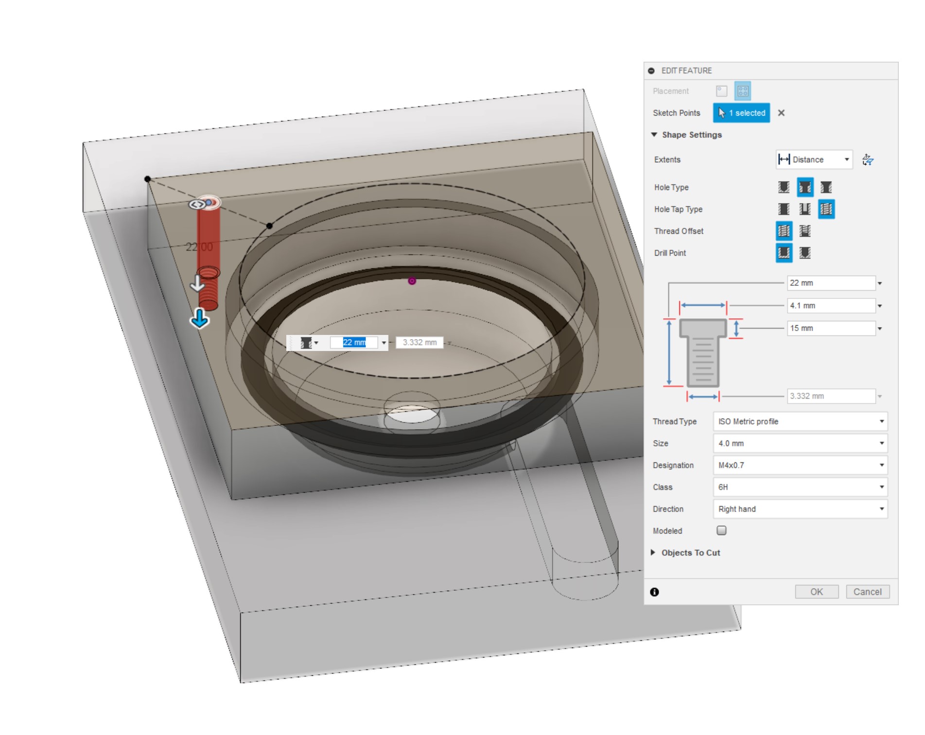
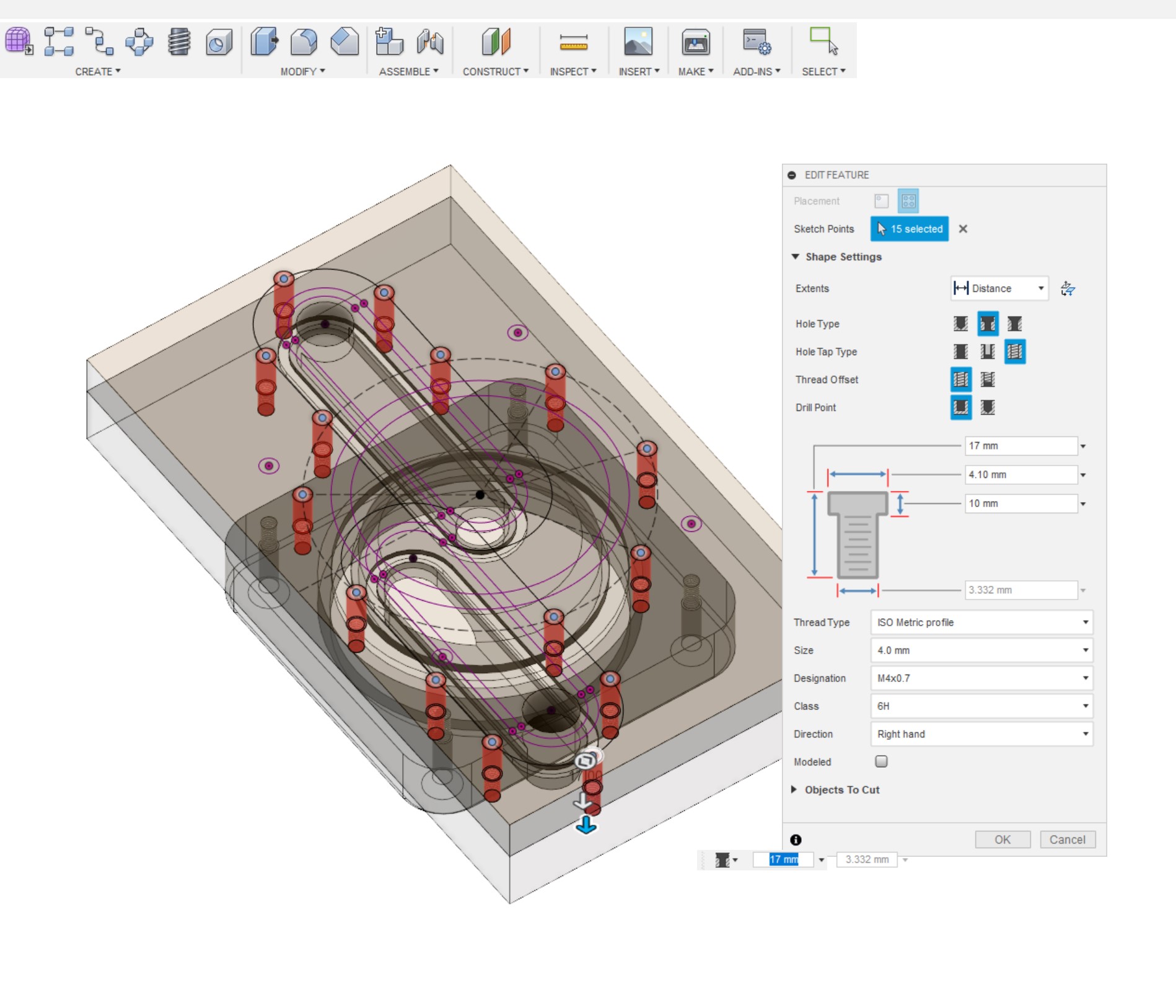
The pump sits inside the bracket nice and snugly, the lip pushing the metal pump head against the O-ring in the groove inside the 'Rear Plate'. To secure it to the distro plate, use the same hole method as for making the distro plate channels watertight. I find four M4 holes with threads drilled to a depth of 7mm in the 'Rear Plate' works very well. They don't need to be spaced perfectly evenly, but it does help. You have a fair bit of flexibility with this design, however.
If you want to get more fancy, you can make slimmer brackets using stronger materials like aluminium; it's an area with a lot of scope for change and originality, and you only have to look at the breadth of available products for confirmation of that!


MSI MPG Velox 100R Chassis Review
October 14 2021 | 15:04


Want to comment? Please log in.