Main junction box...
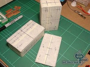
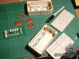
Here are two other chromed plastic project boxes (and lids) marked for drilling. There were going to be quite a few holes of varying sizes. I also began marking up the insides with a marker so I would know what wires were coming in where, and where to place all my circuit boards. I cut up some basic circuit board and used coloured markers to show my 12v/5v/GND sections (I later used green for the 12v - yellow just didn't show up well). I ended up changing these to a board that had larger holes/traces as the wire I decided to use didn't fit well through the holes - even then I still had to use a round needle file to ream the holes slightly.
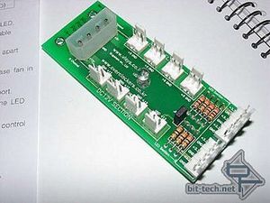
This is a Multi-Power Port (MPP) from www.pccasegear.com a basic power splitter. It takes a molex and gives you four 12v and four 5v lines (designed for fans) and six '3.3v' for LEDs - However, I put a multimeter across the 3.3v terminals and got a reading of 12v! So I used a resister on these for LEDs@12v (electronics novice that I am, I wanted to be safe and the brightness seemed unchanged when I tested them). I opted to use the MPP solely to power LEDs from all of its power connectors simply to minimise the amount of wiring it looked like I would have to do. There was also a blue indicator LED on the PCB - later replaced with a White one and wires extended to a chrome holder on the outside of the junction box.
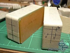
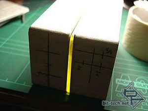
The plan was to have the boxes screwed together with a neon Perspex divider that I could light up. You can see in the right-hand image above my desk lamp shining through from the top and it shows the sort of effect I wanted to achieve - but lit from inside. This is just my desk lamp shining through from the top but gives an idea of what I want to achieve.
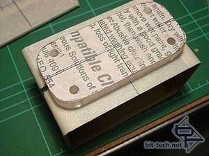
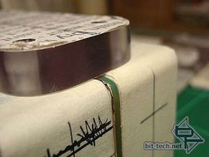
I made a mounting block from a piece of ½" Lexan. After asking nicely, I got a number of small pieces of this for free from the off-cuts bin at the plastics supplier I go to. I cut it out with a hacksaw and filed the edges and corners before sanding and polishing. The holes are 6mm drilled using a drill-press and Plexi-Point drill bit. The edges came out nicely and I had cut the block so it would fit just inside the corner curve of the boxes and not overhang (an overhang just didn't look right when I was messing about test-fitting and thinking up ideas for the mounting).
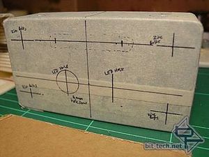
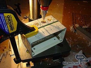
The back of one box showing location of screw holes, LED holes (for the centre divider lighting) and holes in the top to pass wiring through. I drilled the bottom of the boxes for the stainless steel hose (you can see the small pilot holes to allow accurate lining-up of the step drill). You can see in the right hand picture how I had already used screws to join the whole assembly together. This gave the box more stability during the drilling process and allowed me to drill pilot holes through both the boxes and the divider that lined up perfectly. The box was then taken apart and these remaining pilot holes were enlarged on each piece individually due to a requirement for different sized holes.


Here are two other chromed plastic project boxes (and lids) marked for drilling. There were going to be quite a few holes of varying sizes. I also began marking up the insides with a marker so I would know what wires were coming in where, and where to place all my circuit boards. I cut up some basic circuit board and used coloured markers to show my 12v/5v/GND sections (I later used green for the 12v - yellow just didn't show up well). I ended up changing these to a board that had larger holes/traces as the wire I decided to use didn't fit well through the holes - even then I still had to use a round needle file to ream the holes slightly.

This is a Multi-Power Port (MPP) from www.pccasegear.com a basic power splitter. It takes a molex and gives you four 12v and four 5v lines (designed for fans) and six '3.3v' for LEDs - However, I put a multimeter across the 3.3v terminals and got a reading of 12v! So I used a resister on these for LEDs@12v (electronics novice that I am, I wanted to be safe and the brightness seemed unchanged when I tested them). I opted to use the MPP solely to power LEDs from all of its power connectors simply to minimise the amount of wiring it looked like I would have to do. There was also a blue indicator LED on the PCB - later replaced with a White one and wires extended to a chrome holder on the outside of the junction box.


The plan was to have the boxes screwed together with a neon Perspex divider that I could light up. You can see in the right-hand image above my desk lamp shining through from the top and it shows the sort of effect I wanted to achieve - but lit from inside. This is just my desk lamp shining through from the top but gives an idea of what I want to achieve.


I made a mounting block from a piece of ½" Lexan. After asking nicely, I got a number of small pieces of this for free from the off-cuts bin at the plastics supplier I go to. I cut it out with a hacksaw and filed the edges and corners before sanding and polishing. The holes are 6mm drilled using a drill-press and Plexi-Point drill bit. The edges came out nicely and I had cut the block so it would fit just inside the corner curve of the boxes and not overhang (an overhang just didn't look right when I was messing about test-fitting and thinking up ideas for the mounting).


The back of one box showing location of screw holes, LED holes (for the centre divider lighting) and holes in the top to pass wiring through. I drilled the bottom of the boxes for the stainless steel hose (you can see the small pilot holes to allow accurate lining-up of the step drill). You can see in the right hand picture how I had already used screws to join the whole assembly together. This gave the box more stability during the drilling process and allowed me to drill pilot holes through both the boxes and the divider that lined up perfectly. The box was then taken apart and these remaining pilot holes were enlarged on each piece individually due to a requirement for different sized holes.

MSI MPG Velox 100R Chassis Review
October 14 2021 | 15:04


Want to comment? Please log in.