
How DisplayPort works:
DisplayPort uses a unique micro-packet architecture which gives display manufacturers the opportunity to implement new display features and usage models going forward. These could include things like addressable displays, multiple streams and doing much more than you can with a display based on existing raster-scan architectures.Electrically, the interface is similar to PCI-Express’ physical layer connection and is what’s known as an AC-coupled voltage-differential interface. It consists of three different channels: main link, AUX channel and hot plug detect. The main link features one, two or four scalable data pairs (or lanes) fixed at either 1.6Gbit/sec or 2.7Gbit/sec. The main link rate will be determined by a number of factors, including the capabilities of the transmitter and receiver (i.e. Display and Graphics Card) and the quality of the cable.
With DVI, there was a separate pair of lanes responsible for maintaining the data clock, but with DisplayPort the clock is embedded into the data pairs and is extracted from the encoded data stream itself. In the past, colour channels were split over data pairs, but each lane in the DisplayPort interface is decoupled from both the pixel bit depth (bits per pixel, bpp) and the component bit depth (bits per component, bpc). The link supports component bit depths from six (18-bit RGB) to sixteen (48-bit RGB) – it’s questionable whether you’ll see much difference in quality once you get past 10bpc, but that’s beyond the scope of this article.
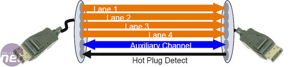 The auxiliary channel is a half-duplex and bi-directional link that has 1Mbit/sec of bandwidth available in version 1.1 of the DisplayPort specification – this will be used for command and control functions sent across the interface. VESA has said that it plans to increase the speed of this channel dramatically in future versions of the specification.
More bandwidth over the auxiliary channel would allow the channel to be used for more bandwidth-intensive applications like webcams, microphones, speakers and even USB hubs. This would mean that all data going to and from the monitor – regardless of whether it’s video information, audio or data from a storage device connected to a display’s embedded USB hub – will travel over a single cable.
 The diagram to the right gives you an idea of the layered nature of the DisplayPort architecture. At the top, the DPCD (DisplayPort configuration data) in the display describes the receiver’s capabilities and stores the display’s connection status. The EDID, on the other hand, tells the source device (usually the PC) of the display’s capabilities once it is connected. Just below this, the link and stream policy makers manage the link and the stream respectively.
At the bottom of the flow diagram, there are the link and physical (PHY) layers. The link layer is responsible for the isochronous transport and link and device services.
In the output device (i.e. the graphics card), the isochronous transport service maps the video and audio streams into a format with a set of rules that the main link will understand – the reason for this is so that the data can scale across the number of lanes available in the main link. Additionally, when the data reaches the display, the rules allow the streams to be reconstructed into their original format.
The link service is used to discover, configure and maintain the link with devices it connects to – it does this using DPCD via the auxiliary channel. When hot-plugging is detected via the hot-plug channel, the PC (or other source device) reads the capabilities of the display via the DPCD and then configures the link though what is known as Link Training.
Link Training is a process where the correct number of lanes are enabled at the right link rate via a handshake between the DisplayPort transmitter (display) and receiver (graphics card) over the auxiliary channel. After Link Training has been completed during normal operation, the display will use the hot-plug lane to detect changes - for example, when a loss of synchronisation is detected.
The device service is used to simply support device-level applications like EDID access and MCCS (Monitor Control Command Set) support via read and write transactions over the auxiliary channel.
Finally, the PHY layer is split up into two sub-blocks, Logical and Electrical, with the logical portion of the layer focused on scrambling/descrambling or encoding/decoding of data. The electrical portion of the PHY layer is responsible for serialisation/de-serialisation, current driving and receiving, and pre-emphasis/equalisation for the main link.
The specification outlines that the bit error rate must be kept under control, even over a 15-metre cable – the maximum cable length supported by v1.1 of DisplayPort. VESA’s representatives have said that the way that the PHY layer has been designed should mean that there is less EMI. Things like the embedded clock channel, the fewer lanes and also the scrambling of data before it’s encoded, which removes the need for a fixed serial bit pattern, will help to reduce EMI according several members of the promoter group.


MSI MPG Velox 100R Chassis Review
October 14 2021 | 15:04


Want to comment? Please log in.