
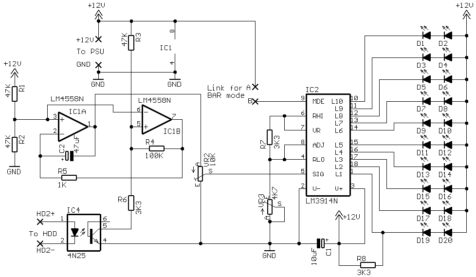
20 LED versions
In this design the effect is of a pair of LEDs moving away from each other, (DOT mode), or, if using BAR mode, a row of LEDs expanding outwards away from each other.
Parts List with order codes for UK and US suppliers
Component layout - top view.
Track layout - Viewed from above.
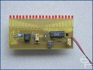
The finished board.
Component layout - top view (left) and Track layout - Viewed from above (right)
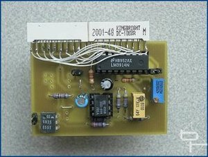
The finished board.
Wiring detail between the LED arrays viewed from above.
In this design the effect is of a pair of LEDs moving away from each other, (DOT mode), or, if using BAR mode, a row of LEDs expanding outwards away from each other.
Parts List with order codes for UK and US suppliers
20 individual LED version
As in all the board designs for the HDD meter, R3 is fitted in its alternate position and VR1 is replaced with a wire link. There is a total of three links on this board.Component layout - top view.
Track layout - Viewed from above.
The finished board.
The PCB layout if using two 10 LED arrays
Again three links are used here. 
Component layout - top view (left) and Track layout - Viewed from above (right)
The finished board.
Wiring detail between the LED arrays viewed from above.
RELATED ARTICLES


MSI MPG Velox 100R Chassis Review
October 14 2021 | 15:04


Want to comment? Please log in.