
Making your own Watercooling Reservoir
I'll be honest - I haven't been very impressed with most of the commercially available reservoirs for water-cooling systems. Whatever you buy, you're limited to their layout and design in your build. Especially since I've been involved in making my own cases, making my own reservoir to my own size/layout has worked well for me. I have tried and used T-lines before, but frankly I don't like them. I much prefer like the ease of bleeding and filling associated with reservoirs.With that in mind, I wanted to take a bit of time to explain a bit more in-depth how to make a reservoir. There are many ways to make reservoirs and mine is only one way, however I know this way is reliable with over several years of trial and error. This is a reservoir that most modders can manage with regular hand power tools.
In that respect, making your own res will probably cost you a bit more up front in terms of tools, and it takes some time to get used to, but it gives you a flexibility in design and options that you simply cannot buy, not to mention transferrable skills to other mod-projects. Usually when I buy materials to make a reservoir, I can make 2-3 identical reservoirs for the same cost it takes to buy a commercially made one.
Reservoir Design
I first decide how to best fit a reservoir into the case and loop I am working on. One of the reasons for making a custom reservoir in the first place is to tailor it to the case and loop, not vice versa. Once I have the barb placement figured out, then I design the internals. I like the top of the reservoir to go directly to a top mounted fillport for easy filling and also a bottom barb to go to the pump inlet. In general, a general rule of thumb is that reservoirs should go as close to the top of the loop as possible to weed out the air bubbles quickly.When it comes to designing the internals, I want the water to have a change of direction, avoiding an easy, direct path to the outlet/pump inlet. If it's simple for the water to go from one barb internally to the next, it will take air with it and the loop will be slower to bleed. Co-operatively, I also allow a place for air to trap at the top of the res and not get trapped under internal fixings.
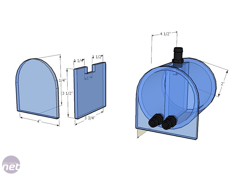
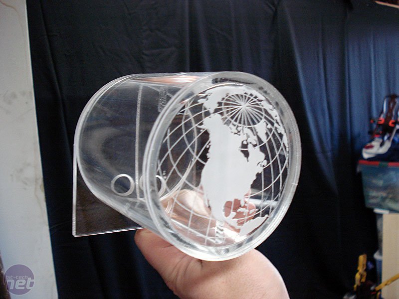
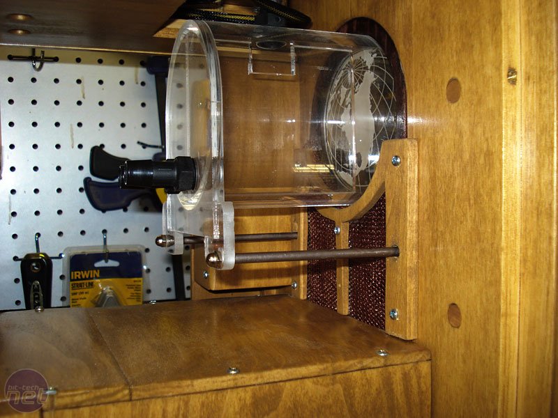
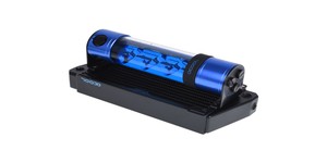
Here are a few pictures of the last reservoir that I made - it's one I've used for over a year. I used 4in cast acrylic tube mounted horizontally, with a 1/4in gap between the divider and the front of the res, so that water has to go through from one barb to another before the exit. This design has worked very well in bleeding quickly since the water has to travel a greater distance which gives air time to easily rise to the top. The globe etching in the front was courtesy of Dennis at Dangerden.
Click to enlarge
Click to enlarge
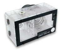
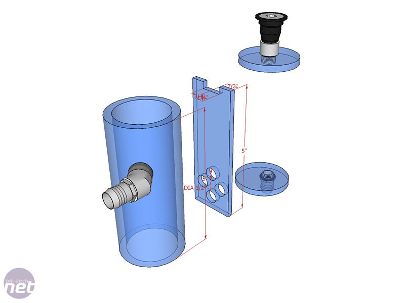 On the reservoir I am made for the Zenith radio case project, I decided on a narrow 2.25in OD 1.75in ID cylindrical tube that was 5.5in long in total, or 5in minus end the caps. The barb going into the reservoir is placed particularly high so it was above the tubing from the CPU waterblock, keeping the build looking neat.
I wanted the reservoir inlet to be above the CPU block so that air doesn't get trapped in the CPU block. Inside I made an internal divider so that the water will hit before it and slow down it goes anywhere else, allowing time for any air bubbles to float upwards.
I also placed a few holes further down in the divider that are 3/8in diameter to let water through but were restrictive enough to help keep air from heading straight toward the outlet.
This divider doesn't quite go all the way down to the bottom as there is about a 1/32in gap between it and the bottom so that both sides will drain.


MSI MPG Velox 100R Chassis Review
October 14 2021 | 15:04


Want to comment? Please log in.